2014 HVAC
Heating & Air Conditioning - Service Information - Challenger
DESCRIPTION
DESCRIPTION
An Automatic Temperature Control (ATC) single zone heating and A/C system is standard equipment on this vehicle.
To maintain the performance level of the Heating, Ventilation and Air Conditioning (HVAC) system, the engine cooling system must be properly maintained. The use of a bug screen is not recommended. Any obstructions in front of the radiator or A/C condenser will reduce the performance of the A/C and engine cooling systems.
The engine cooling system includes the radiator, thermostat, radiator hoses and the engine coolant pump. See the ENGINE COOLING SYSTEM article for more information before opening or attempting any service to the engine cooling system.

Courtesy of CHRYSLER GROUP, LLC
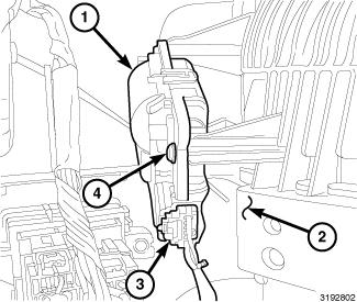
This vehicle is equipped with a HVAC housing (1) that combines heating, ventilation and A/C capabilities into a single unit, mounted within the passenger compartment, behind the instrument panel. The HVAC housing includes:
- Recirculation-air door and actuator (2)
- Blower motor (3)
- Blower motor power module (4)
- Evaporator temperature sensor (5)
- Mode-air doors and actuator (6)
- Blend-air door and actuator (7)
- Heater core (8)
- A/C evaporator (9)
Based upon the system and selected mode, conditioned air can exit the HVAC housing through one or a combination of the three main housing outlets: defrost, panel or floor. The defrost and panel outlets are located on the top of the HVAC housing and the floor outlets are located on the bottom of the HVAC housing. Once the conditioned air exits the HVAC housing, it is further directed through molded plastic ducts to the outlets within the vehicle interior. These outlets and their locations are as follows:
- Defroster Outlets - Two large defroster outlets are located near the center of the instrument panel top cover, near the base of the windshield.
- Side Window Demister Outlets - There are two side window demister outlets, one is located at each outboard end of the instrument panel top cover, near the belt line at the A-pillars.
- Panel Outlets - There are four panel outlets in the instrument panel, one located near each outboard end of the instrument panel facing the rear of the vehicle and one located on each side of the instrument panel center bezel.
- Floor Outlets - There is one floor outlet located above each side of the floor panel center tunnel near the dash panel. There is also one outlet located under each front seat.
- Console Outlets - There are two console outlets located at the back of the center floor console facing the rear of the vehicle.
OPERATION
OPERATION
The Automatic Temperature Control (ATC) heating and A/C system is a blend-air type system. In a blend-air system, a blend-air door controls the amount of conditioned air that is allowed to flow through, or around, the heater core. The temperature control determines the discharge air temperature by operating the blend door actuator, which moves the blend-air door. This design allows almost immediate control of output air temperature.
Courtesy of CHRYSLER GROUP, LLC
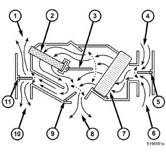
The heating and A/C system pulls outside (ambient) air through the fresh air intake (4) located at the cowl panel at the base of the windshield and into the air inlet housing above the Heating, Ventilation and Air Conditioning (HVAC) housing and then passes through the A/C evaporator (7). Air flow is then directed either through or around the heater core (2). This is done by adjusting the position of the blend-air door (3) with the temperature control located on the A/C-heater control in the instrument panel. Air flow is then directed out the floor outlet (8), instrument panel outlet (10) or the defroster outlet (1) in various combinations by adjusting the position of the mode-air doors (9 and 11) using the mode control located on the A/C-heater control. The temperature and mode control uses electrical actuators to operate the air doors.
The velocity of the air flow out of the outlets can be adjusted with the blower speed control located on the A/C-heater control.
The fresh air intake can be shut off by pressing the Recirculation button on the A/C-heater control. This will operate the electrically actuated recirculation-air door (5), which closes off the fresh air intake. With the fresh air intake closed, the conditioned air within the vehicle is pulled back into the HVAC housing through the recirculation air intake (6) located within the passenger compartment.
The A/C compressor can be engaged by pressing the A/C (snowflake) button on the A/C-heater control. It will automatically engage when the mode control is set in any Floor to Defrost position. This will remove heat and humidity from the air before it is directed through or around the heater core. The mode control on the A/C-heater control is used to direct the conditioned air to the selected system outlets.
The two slot-type defroster outlets receive airflow from the HVAC housing through the molded plastic defroster ducts, which connect to the HVAC housing defroster outlets. The airflow from the defroster outlets is directed by fixed vanes in the defroster outlet grilles and cannot be adjusted. The defroster outlet grilles are integral to the instrument panel top cover.
The side window demister outlets receive airflow from the HVAC housing through the molded plastic demister ducts. The demisters direct air from the HVAC housing through the outlets located on the top corners of the instrument panel. The airflow from the side window demister outlets is directed by fixed vanes in the demister outlet grilles and cannot be adjusted. The side window demister outlet grilles are serviceable from the instrument panel. The demisters operate when the controls are set in Heat, Floor, Mix and Defrost modes.
The four instrument panel outlets receive airflow from the HVAC housing through two molded plastic main panel ducts. One duct directs air flow out of the right side instrument panel outlets, while the other duct delivers air flow to the left side outlets. Each of these outlets can be individually adjusted to direct the flow of air.
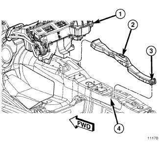
The floor outlets receive airflow from the HVAC housing through the floor distribution ducts which are integral to the rear cover of the HVAC air distribution housing. Two plastic rear distribution ducts and one center console duct attach to the rear cover and provide conditioned air to the rear seating positions. The two console outlets can be individually adjusted to direct the flow of air, but the floor outlets cannot be adjusted.
It is important to keep the HVAC air intake opening clear of debris.
Leaf particles and other debris that is small enough to pass through the
cowl opening screen can accumulate within the HVAC housing. The closed,
warm, damp and dark environment created within the housing is ideal for
the growth of certain molds, mildews and other fungi. Any accumulation
of decaying plant matter provides an additional food source for fungal
spores, which enter the housing with the fresh intake-air. Excess
debris, as well as objectionable odors created by decaying plant matter
and growing fungi can be discharged into the passenger compartment
during heater-A/C operation if the air intake opening is not kept clear
of debris.
NOTE:
The A/C system is designed for the use of an A/C expansion valve to meter the flow of refrigerant to the A/C evaporator. The A/C evaporator cools and dehumidifies the incoming air prior to blending it with the heated air. To maintain minimum evaporator temperatures and prevent evaporator freezing, an evaporator temperature sensor is used. The sensor is located downstream of the evaporator and supplies an evaporator temperature signal to the A/C-heater control. The A/C-heater control broadcasts the A/C request on the Controller Area Network (CAN) B bus, where it is read and processed by the Totally Integrated Power Module (TIPM), which in turn broadcasts the A/C request on the CAN C bus, where it is read and processed by the Powertrain Control Module (PCM).
DIAGNOSIS AND TESTING
A/C PERFORMANCE
The A/C system is designed to provide the passenger compartment with low temperature and low humidity air. The A/C evaporator, located in the Heating, Ventilation and Air Conditioning (HVAC) housing is cooled to temperatures near the freezing point. As warm damp air passes over the fins of the A/C evaporator, the air transfers its heat to the refrigerant in the evaporator coils and the moisture in the air condenses on the evaporator fins. During periods of high heat and humidity, an A/C system will be more effective in the Recirculation mode (max A/C). With the system in the Recirculation mode, only air from the passenger compartment passes through the A/C evaporator. As the passenger compartment air dehumidifies, the A/C system performance levels rise.
Humidity has an important bearing on the temperature of the air delivered to the interior of the vehicle. It is important to understand the effect that humidity has on the performance of the A/C system. When humidity is high, the A/C evaporator has to perform a double duty. It must lower the air temperature, and it must lower the temperature of the moisture in the air that condenses on the evaporator fins. Condensing the moisture in the air transfers heat energy into the evaporator fins and coils. This reduces the amount of heat the A/C evaporator can absorb from the air. High humidity greatly reduces the ability of the A/C evaporator to lower the temperature of the air.
However, evaporator capacity used to reduce the amount of moisture in the air is not wasted. Wringing some of the moisture out of the air entering the vehicle adds to the comfort of the passengers. Although, an owner may expect too much from their A/C system on humid days. A performance test is the best way to determine whether the system is performing up to design standards. This test also provides valuable clues as to the possible cause of trouble with the A/C system.
A/C PERFORMANCE TEST
Review the warnings and cautions for this system before performing
the procedure. Failure to follow these instructions may result in
serious injury or death.
WARNING:
- Make sure the following conditions are met in the area where this test is to be performed:
- Maximum ambient temperature: 43.3°C (110°F)
- Minimum ambient temperature: 15.5°C (60°F)
- Maximum relative humidity: 90%
- Minimum relative humidity: 20%
- Operate the heating and A/C system under the following conditions.
- Engine at normal operating temperature
- Engine at normal idle speed
- No sun-load in the cabin of the vehicle
- Vehicle doors and windows closed
- Transmission in Park or Neutral with the parking brake set (depending on transmission application)
- A/C heater controls set to Recirculation mode, full cool, panel mode, high blower and with A/C compressor engaged. If the A/C compressor does not engage, see the A/C System Diagnosis table
- All panel outlet vanes open and positioned straight rearward
NOTE: If the following step is not performed, the results of this test will not be accurate.
- Using a scan tool, operate the engine cooling fans at high speed from the Totally Integrated Power Module (TIPM) Electronic Control Unit (ECU) view.
- Insert a thermometer in the driver side center panel air outlet and
operate the A/C system until the thermometer temperature stabilizes or a
minimum of five minutes.
NOTE: This procedure requires you to know what the temperature and relative humidity is in your location at the time of the test. This information can be obtained from multiple sources, such as the Internet or local news media.
- With the A/C clutch engaged, compare the observed panel outlet air temperature along with ambient temperature and the relative humidity of the work area to the Maximum Panel Outlet Temperature chart.
- If the air outlet temperature fails to meet the specifications in the Maximum Panel Outlet Temperature chart, see the A/C System Diagnosis table.

Courtesy of CHRYSLER GROUP, LLC
A/C SYSTEM DIAGNOSIS
Condition
Possible Causes
Correction
Rapid A/C clutch cycling (ten or more cycles per minute).
1. Low refrigerant system charge.
1. See Refrigerant System Leaks. Refer to PLUMBING, DIAGNOSIS AND TESTING. Test the refrigerant system for leaks. Repair, evacuate and charge the refrigerant system, if required.
Equal pressures, but the A/C clutch does not engage.
1. No refrigerant in the refrigerant system.
1. See Refrigerant System Leaks. Refer to PLUMBING, DIAGNOSIS AND TESTING. Test the refrigerant system for leaks. Repair, evacuate and charge the refrigerant system, if required.
2. Open fuse.
2. See appropriate
wiring information. Check the fuses in the Totally Integrated Power
Module (TIPM) and the rear Power Distribution Center (PDC). Repair the
shorted circuit or component and replace the fuse(s), if required.
3. Inoperative A/C clutch.
3. See A/C Compressor DIAGNOSIS AND TESTING. Test the A/C clutch and coil and replace, if required.
4. Improperly installed or inoperative evaporator temperature sensor.
4. See SENSOR, EVAPORATOR TEMPERATURE
. Test the sensor and replace, if required.
5. Inoperative A/C pressure transducer.
5. See TRANSDUCER, A/C PRESSURE
. Test the sensor and replace, if required.
6. Inoperative Powertrain Control Module (PCM).
6. See the DTC INDEX
article
. Test the PCM and replace, if required.
Normal pressures, but A/C Performance Test air temperatures at center panel outlet are too high.
1. Excessive refrigerant oil in system.
1. See OIL, REFRIGERANT
Level
. Recover the refrigerant from the refrigerant system and inspect the
refrigerant oil content. Restore the refrigerant oil to the proper
level, if required.
2. Blend door actuator improperly installed or inoperative.
2. See ACTUATOR, BLEND DOOR
. Inspect the actuator for proper operation and replace, if required.
3. Blend-air door inoperative or sealing improperly.
3. See HOUSING, HVAC
. Inspect the blend-air door for proper operation and sealing. Repair if required.
The low side pressure is normal or slightly low, and the high side pressure is too low.
1. Low refrigerant system charge.
1. See Refrigerant System Leaks
. Refer to PLUMBING, DIAGNOSIS AND TESTING. Test the refrigerant system for leaks. Repair, evacuate and charge the refrigerant system, if required.
2. Refrigerant flow through the A/C evaporator is restricted.
2. See EVAPORATOR, A/C
. Replace the restricted A/C evaporator, if required.
3. Inoperative A/C compressor.
3. See COMPRESSOR, A/C
. Replace the A/C compressor, if required.
The low side pressure is normal or slightly high, and the high side pressure is too high.
1. A/C condenser air flow restricted.
1. See CONDENSER, A/C
. Check the A/C condenser for damaged fins, foreign objects obstructing
air flow through the condenser fins, and missing or improperly installed
air seals. Clean, repair, or replace components as required.
2. Refrigerant flow through the A/C receiver/drier is restricted.
2. See A/C Receiver/Drier in this group. Replace the restricted A/C receiver/drier, if required.
3. Inoperative radiator cooling fans.
3. See ENGINE COOLING SYSTEM
. Test the radiator cooling fans and replace, if required.
4. Refrigerant system overcharged.
4. See Refrigerant System Charge. Refer to STANDARD PROCEDURE
. Recover the refrigerant from the refrigerant system. Charge the refrigerant system to the proper level, if required.
5. Air in the refrigerant system.
5. See Refrigerant System Leaks in this group. Refer to PLUMBING, DIAGNOSIS AND TESTING. Test the refrigerant system for leaks. Repair, evacuate and charge the refrigerant system, if required.
6. Engine overheating.
6. See ENGINE COOLING SYSTEM
. Test the engine cooling system and repair, if required.
The low side pressure is too high, and the high side pressure is too low.
1. Accessory drive belt slipping.
1. See ENGINE COOLING SYSTEM
. Inspect the accessory drive belt condition and tension. Repair as required.
2. Inoperative A/C expansion valve.
2. See A/C Expansion Valve in this group. Test and replace the valve, if required.
3. Inoperative A/C compressor.
3. See COMPRESSOR, A/C
. Replace the A/C compressor, if required.
The low side pressure is too low, and the high side pressure is too high.
1. Restricted refrigerant flow through the refrigerant lines.
1. See LINE, A/C LIQUID, LINE, A/C SUCTION and LINE, A/C DISCHARGE
. Inspect the refrigerant lines for kinks, tight bends or improper
routing. Correct the routing or replace the refrigerant line, if
required.
2. Restricted refrigerant flow through the A/C expansion valve.
2. See VALVE, A/C EXPANSION
. Test and replace the valve, if required.
3. Restricted refrigerant flow through the A/C condenser.
3. See CONDENSER, A/C
. Replace the restricted A/C condenser, if required.
HEATER PERFORMANCE
See ENGINE COOLING SYSTEM before performing the following tests. Check the engine coolant level and flow, engine coolant reserve/recovery system operation, accessory drive belt condition and tension, radiator air flow and the fan drive operation. Perform the A/C System Performance Test, found within the HVAC System Test. Refer to STANDARD PROCEDURE . If any Diagnostic Trouble Codes (DTCs) are found in the A/C-heater control or Powertrain Control Module (PCM), repair as necessary.
MAXIMUM HEATER OUTPUT
Engine coolant is delivered to the heater core through two heater hoses. With the engine idling at normal operating temperature, set the temperature control to the full hot position, the mode control to the floor position, and the blower motor control to the highest speed position. Using a test thermometer, check the temperature of the air being discharged at the front floor outlets. Compare the test thermometer reading to the Heater Temperature Reference chart.
HEATER TEMPERATURE REFERENCE
Ambient Air Temperature
16° C
(60° F)21° C
(70° F)27° C
(80° F)32° C
(90° F)
Minimum Heater System Air Outlet Temperature
52° C
(125° F)56° C
(133° F)59° C
(139° F)62° C
(144° F)
See ENGINE COOLING SYSTEM if the heater outlet air temperature is below the minimum specification. Both of the heater hoses should be hot to the touch. The coolant return heater hose should be slightly cooler than the coolant supply heater hose. If the return hose is much cooler than the supply hose, locate and repair the engine coolant flow obstruction in the cooling system.
OBSTRUCTED COOLANT FLOW
Possible locations or causes of obstructed coolant flow are as follows:
- Inoperative water pump.
- Inoperative thermostat.
- Pinched or kinked heater hoses.
- Improper heater hose routing.
- Plugged heater hoses or supply and return ports at the cooling system connections.
- Plugged heater core.
If proper coolant flow through the cooling system is verified, and heater outlet air temperature is low, a mechanical problem may exist.
MECHANICAL PROBLEMS
Possible locations or causes of insufficient heat due to mechanical problems are as follows:
- Obstructed cowl air intake.
- Obstructed heater system outlets.
- Inoperative engine thermostat.
- Inoperative blower motor system.
- Inoperative A/C-heater control.
- Inoperative blend door actuator.
- Inoperative, obstructed or improperly installed blend-air door.
TEMPERATURE CONTROL
If the heater outlet air temperature cannot be adjusted with the temperature control on the A/C-heater control, the following could require service:
- Inoperative A/C-heater control.
- Inoperative blend door actuator.
- Inoperative, obstructed or improperly installed blend-air door.
- Improper engine coolant temperature.
- Inoperative related wiring harness or connectors.
STANDARD PROCEDURE
STANDARD PROCEDURE - A/C EVAPORATOR CLEANING
Some vehicle operators may experience a musty odor from the A/C system, primarily at start up in hot and humid climates. This odor may be the result of microbial growth on the cooling coil. During normal A/C system operation, condensation forms in and around the A/C cooling coil. When airborne pollutants mix with this condensation, bacteria and fungi growth begins and odor may result.
If the vehicle operator experiences a musty odor when operating the A/C system, perform the following procedure.
Always use eye protection, rubber gloves and protective clothing when
performing the following procedure. Avoid continuous breathing of
vapors from evaporator coil cleaning and sealing fluids. Avoid contact
with skin and eyes. Failure to follow these instruction may result in
possible serious or fatal injury.
WARNING:
- On models equipped with a cabin air filter, remove the filter and inspect for dirt and debris. Refer to FILTER, CABIN AIR, REMOVAL. Discard the used cabin filter if required.
- Remove the cowl panel cover (refer to COVER, COWL PANEL for more information).
- Clean any dirt and debris that may be present at the HVAC fresh air inlet screen and at the top of the cowl panel.
- Install the cowl panel cover.
- Raise and support the vehicle.
- Inspect the evaporator drain hose or tube (depending on application) for foreign material that may be blocking the drain and repair as necessary.
- Once drain operation has been verified;
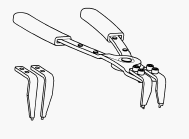
- when equipped with a rubber drain hose, temporarily pinch the drain hose closed using an appropriate pair of heater hose pliers.
- when equipped with a solid plastic drain tube, obtain an appropriate size rubber or plastic cap or plug and temporarily cap or plug the drain tube.
- Lower the vehicle.
- Place a protective cover over the front passenger side floor and seat area.
- Remove the blower motor. Refer to MOTOR, BLOWER, REMOVAL.
- Remove the blower motor power module. Refer to MODULE, POWER, BLOWER MOTOR, REMOVAL.
- Clean any dirt and debris that may be present inside the HVAC blower motor housing and all readily accessible areas inside the HVAC housing. If necessary, use a vacuum with a small flexible hose, and take caution not to damage the evaporator core fins.
- Using PSE Flex Spray Delivery Tool 534-62637 or equivalent, completely coat the entire surface of A/C evaporator with three bottles of Mopar® Cooling Coil Cleaner through the blower motor and power module or resistor openings. Be sure to use all of the coil cleaner in each container.
- Allow the vehicle to sit for 30 minutes.
- Raise and support the vehicle.
WARNING: Excess cooling coil cleaner will drain from the evaporator housing when the clamp, cap or plug is removed from the evaporator drain hose or tube. Always use eye protection, rubber gloves and protective clothing. Avoid continuous breathing of vapors from evaporator coil cleaning fluid. Avoid contact with skin and eyes. Failure to follow these instruction may result in possible serious or fatal injury.
- Remove the previously installed clamp, cap or plug from the evaporator drain hose or tube and allow excess coil cleaner to drain from the HVAC housing.
- Lower the vehicle.
- Refill the three empty coil cleaner bottles with clean tap water.
- Using PSE Flex Spray Delivery Tool 534-62637 or equivalent, completely rinse the entire surface of A/C evaporator with the three bottles of clean tap water through the blower motor and power module openings. Be sure to use all of the water in each container.
- Install the blower motor. Refer to MOTOR, BLOWER, INSTALLATION.
- Install the blower motor power module. Refer to MODULE, POWER, BLOWER MOTOR, INSTALLATION.
- Disconnect the wire harness connector from the A/C compressor to disable compressor operation. Refer to COMPRESSOR, A/C, REMOVAL.
- Start the engine
- Adjust all the windows so they are open approximately 8 mm (0.5 in.).
- Set the A/C heater controls to the following:
- air distribution to Panel and Recirculation mode
- temperature to full heat
- Allow the vehicle to run for 20 minutes.
- Turn the engine off.
- Raise and support the vehicle.
- Inspect the evaporator drain hose or tube (depending on application) for foreign material that may have blocked the drain during evaporator coil cleaning and repair as necessary.
- Once drain operation has been verified;
- when equipped with a rubber drain hose, temporarily pinch the drain hose closed using an appropriate pair of heater hose pliers.
- when equipped with a solid plastic drain tube, obtain an appropriate size rubber or plastic cap or plug and temporarily cap or plug the drain tube.
- Lower the vehicle.
- Remove the blower motor. Refer to MOTOR, BLOWER, REMOVAL.
- Remove the blower motor power module. Refer to MODULE, POWER, BLOWER MOTOR, REMOVAL.
- Using PSE Flex Spray Delivery Tool 534-62637 or equivalent,
completely coat the entire surface of A/C evaporator with one bottle of
Mopar® Cooling Coil Coating through the blower motor and power module
openings. Be sure to use all of the coil coating in the container.
NOTE: Be sure to thoroughly clean out the spray delivery tool with warm water once coil coating is complete to prevent damage to the tool.
- Refill the empty bottles with clean warm tap water and completely rinse out the PSE Flex Spray Delivery Tool 534-62637, or equivalent.
- Allow the vehicle to sit for 30 minutes.
- Install the blower motor. Refer to MOTOR, BLOWER, INSTALLATION.
- Install the blower motor power module. Refer to MODULE, POWER, BLOWER MOTOR, INSTALLATION.
- Raise and support the vehicle.
WARNING: Excess cooling coil coating will drain from the evaporator housing when the clamp, cap or plug is removed from the evaporator drain hose or tube. Always use eye protection, rubber gloves and protective clothing. Avoid continuous breathing of vapors from evaporator coil sealing fluid. Avoid contact with skin and eyes. Failure to follow these instruction may result in possible serious or fatal injury.
- Remove the previously installed clamp, cap or plug from the evaporator drain hose or tube and allow excess coil coating to drain from the HVAC housing.
- Lower the vehicle.
- Start the engine
- Adjust all the windows so they are open approximately 8 mm (0.5 in.).
- Set the A/C heater controls to the following:
- air distribution to Panel and Recirculation mode
- temperature to full heat
- Allow the vehicle to run for 20 minutes.
- Turn vehicle off.
- Remove protective cover from front passenger side floor and seat area.
- On models equipped with a cabin air filter, install the filter. Refer to FILTER, CABIN AIR, INSTALLATION.
- Connect the wire harness connector to the A/C compressor. Refer to COMPRESSOR, A/C, INSTALLATION.
- Verify proper heating and A/C system operation.
SPECIFICATIONS
A/C SYSTEM
A/C SYSTEM SPECIFICATIONS
Item
Description
Notes
A/C Clutch Air Gap
0.35 - 0.60 mm (0.014 - 0.024 in.)
All Engines
A/C Clutch Coil Draw
3.2 Max amps @ 12V ± 0.5V @ 21° C (70° F)
5.7L/6.4L Engines
3.1 - 4.0 amps @ 12V ± 0.5V @ 21° C (70° F)
3.6L Engine
A/C Clutch Coil Resistance
3.3 - 3.5 ohms
5.7L/6.4L Engines
3.0 - 4.0 ohms
3.6L Engine
Freeze-up Control
Evaporator Temperature Sensor
HVAC housing mounted
Pressure Control
A/C Pressure Transducer
A/C liquid line mounted
Refrigerant Charge Capacity - R-134a
681 g (1.50 lbs.)
See A/C Underhood Specification Label located in the engine compartment
Refrigerant Charge Capacity - R-1234yf
709 g (1.56 lbs.)
See A/C Underhood Specification Label located in the engine compartment
* Always use the type of PAG oil listed for the model being serviced. See A/C Underhood Specification Label located in the engine compartment. Do not mix different types of PAG oils. Refer to OIL, REFRIGERANT, STANDARD PROCEDURE.
FASTENER TORQUE
FASTENER TORQUE SPECIFICATIONS
Description
N.m
Ft. Lbs.
In. Lbs.
All Screws NOT Listed Below
2
-
17
A/C Compressor to Engine
Specific fastener placement and torque pattern required. Refer to COMPRESSOR, A/C, INSTALLATION.
A/C Condenser to Radiator Bolts
5
-
44
A/C Expansion Valve to Evaporator Tube Tapping Block Bolts
11
-
97
Air Distribution Housing Halves Screws
2.2
-
20
Air Distribution Housing to HVAC Housing Screws
2.2
-
20
Air Inlet Housing to HVAC Housing Screws
2.2
-
20
Blower Motor Screws
2.2
-
20
Compressor Shaft Bolt
19
-
168
Flange to HVAC Housing Screws
2.2
-
20
Floor Console Duct to Floor Panel Screws
2.2
-
20
Fresh Air Inlet Housing to Dash Panel Nuts
7
-
62
Heater Core Retaining Bracket to Air Distribution Housing Screw
2.2
-
20
HVAC Housing Halves Screws
2.2
-
20
HVAC Housing to Engine Side of Dash Panel Nuts
7
-
62
HVAC Housing to Passenger Side of Dash Panel Nuts
3
-
26
Instrument Panel/demister Ducts to Instrument Panel Screw
2.2
-
20
Liquid Line Front to Rear Section Nut
22
16
-
Refrigerant Lines to A/C Expansion Valve Nut
23
17
-
Refrigerant Line to A/C Compressor Nut
23
17
-
Refrigerant Line to A/C Condenser Nut
22
16
-
Refrigerant Line Bracket to Strut Tower Bolt
11
-
97
Receiver/drier to A/C Condenser Bolt
22
16
-
Receiver/drier Bracket to A/C Condenser Screw
5
-
44
Suction Line Front to Rear Section Nut
22
16
-
Strut Support to Strut Tower Bolts
38
28
-
SPECIAL TOOLS
SPECIAL TOOLS

6801 - Terminal Probe
(Originally Shipped In Kit Number(s) 10190.)
9764 - Pliers, A/C Snap Ring
(Originally Shipped In Kit Number(s) 9909.)
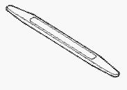
C-4755 - Trim Stick
(Originally Shipped In Kit Number(s) 9299, 9299CC, 9299CC, 9300A-CAN.)
CONTROLS
ACTUATOR, BLEND DOOR
DESCRIPTION
DESCRIPTION
Courtesy of CHRYSLER GROUP, LLC
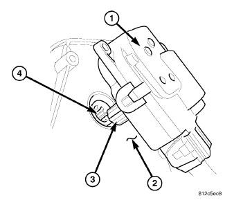
The blend door actuator (1) for the heating and A/C system is a reversible, 12 volt Direct Current (DC) servo motor, which is mechanically connected to the blend-air door. The blend door actuator is located on the left side of the HVAC air distribution housing.
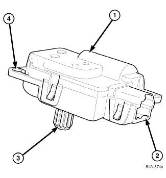
The blend door actuator is interchangeable with the actuators for the mode-air door and the recirculation-air door. Each actuator is contained within an identical black molded plastic housing with an integral wire connector receptacle (2). Each actuator also has an identical output shaft with splines (3) that connect it to its respective door linkage and three integral mounting tabs (4) that allow the actuator to be secured to the HVAC housing. The blend door actuator does not require mechanical indexing to the blend-air door, as it is electronically calibrated by the A/C-heater control.
OPERATION
OPERATION
The blend door actuator is connected to the A/C-heater control through the vehicle electrical system by a dedicated two-wire lead and connector of the HVAC wire harness. The blend door actuator can move the blend-air door in two directions. When the A/C-heater control pulls the voltage on one side of the motor connection high and the other connection low, the blend-air door will move in one direction. When the A/C-heater control reverses the polarity of the voltage to the motor, the blend-air door moves in the opposite direction.
When the A/C-heater control makes the voltage to both connections high or both connections low, the blend-air door stops and will not move. The A/C-heater control uses a pulse-count positioning system to monitor the operation and relative position of the blend door actuator and the blend-air door. The A/C-heater control learns the blend-air doors stop positions during the calibration procedure and will store a diagnostic trouble code (DTC) for any problems it detects in the blend door actuator circuit.
The blend door actuator is diagnosed using a scan tool. Refer to DIAGNOSTIC CODE INDEX .
The blend door actuator cannot be adjusted or repaired and must be replaced if inoperative or damaged.
REMOVAL
REMOVAL
Disable the airbag system before attempting any steering wheel,
steering column, or instrument panel component diagnosis or service.
Disconnect and isolate the negative battery (ground) cable, then wait
two minutes for the airbag system capacitor to discharge before
performing further diagnosis or service. This is the only sure way to
disable the airbag system. Failure to take the proper precautions could
result in accidental airbag deployment and possible serious or fatal
injury.
WARNING:
Courtesy of CHRYSLER GROUP, LLC
- Disconnect and isolate the negative battery cable.
- If equipped, remove the instrument panel silencer from the driver side of the instrument panel.
- Remove the two screws (4) that secure the blend door actuator (1) to the driver side of the HVAC air distribution housing (3).
- Remove the blend door actuator from the air distribution housing, disconnect the HVAC wire harness connector (2) and remove the actuator.
INSTALLATION
INSTALLATION
Courtesy of CHRYSLER GROUP, LLC
- Position the blend door actuator (1) into the vehicle.
- Install the blend door actuator onto the driver side of the HVAC air
distribution housing (4). If necessary, rotate the actuator slightly to
align the splines on the actuator output shaft (2) with those on the
blend door cam (3).
Fig. 7: Actuator-Blend Door-Single/Dual Driver Removal & Installation
Courtesy of CHRYSLER GROUP, LLC - Install the two screws (4) that secure the blend door actuator (1) to the air distribution housing (3). Tighten the screws to 2 N.m (17 in. lbs.).
- Connect the HVAC wire harness connector (2) to the blend door actuator.
- If equipped, install the instrument panel silencer onto the driver side of the instrument panel.
- Reconnect the negative battery cable.
- Initiate the Actuator Calibration function using a scan tool. Refer to STANDARD PROCEDURE .
ACTUATOR, MODE DOOR
DESCRIPTION
DESCRIPTION
Courtesy of CHRYSLER GROUP, LLC
The mode door actuator (1) is a reversible, 12-volt direct current (DC), servo motor. The mode door actuator is located on the driver side end of the HVAC air distribution housing, close to the instrument panel. The mode door actuator is mechanically connected to the floor, defrost/demist and the panel-air doors.
The mode door actuator is interchangeable with the actuators for the blend-air door and the recirculation-air door. Each actuator is contained within an identical black molded plastic housing with an integral wire connector receptacle (2). Each actuator also has an identical output shaft with splines (3) that connect it to its door linkage and three integral mounting tabs (4) that allow the actuator to be secured to the HVAC housing. The mode door actuator does not require mechanical indexing to the mode-air doors, as it is electronically calibrated by the A/C-heater control.
OPERATION
OPERATION
The mode door actuator is connected to the A/C-heater control through the vehicle electrical system by a dedicated two-wire lead and connector of the HVAC wire harness. The mode door actuator can move the floor, defrost/demist and the panel-air doors in two directions. When the A/C-heater control pulls the voltage on one side of the motor connection high and the other connection low, the mode-air doors will move in one direction. When the A/C-heater control reverses the polarity of the voltage to the motor, the mode-air doors moves in the opposite direction.
When the A/C-heater control makes the voltage to both connections high or both connections low, the mode-air doors stop and will not move. The A/C-heater control uses a pulse-count positioning system to monitor the operation and relative position of the mode door actuator and the mode-air doors. The A/C-heater control learns the mode-air doors stop position during the calibration procedure and will store a diagnostic trouble code (DTC) for any problems it detects in the mode door actuator circuits.
The mode door actuator is diagnosed using a scan tool. Refer to DIAGNOSTIC CODE INDEX .
The mode door actuator cannot be adjusted or repaired and must be replaced if inoperative or damaged.
REMOVAL
REMOVAL
Disable the airbag system before attempting any steering wheel,
steering column, or instrument panel component diagnosis or service.
Disconnect and isolate the negative battery (ground) cable, then wait
two minutes for the airbag system capacitor to discharge before
performing further diagnosis or service. This is the only sure way to
disable the airbag system. Failure to take the proper precautions could
result in accidental airbag deployment and possible serious or fatal
injury.
WARNING:
Courtesy of CHRYSLER GROUP, LLC
- Disconnect and isolate the negative battery cable.
- Remove the instrument panel silencer from the driver side of the instrument panel. Refer to PANEL, SILENCER, REMOVAL .
- Remove the screws (1) that secure the mode door actuator (2) to the driver side of the HVAC air distribution housing (3).
- Remove the mode door actuator from the air distribution housing and disconnect the HVAC wire harness connector (4) and remove the actuator from the vehicle.
INSTALLATION
INSTALLATION
Courtesy of CHRYSLER GROUP, LLC
- Position the mode door actuator (1) into the vehicle.
- Install the mode door actuator onto the driver side of the HVAC air
distribution housing (2). If necessary, rotate the actuator slightly to
align the splines on the actuator output shaft (3) with those on the
mode door cam (4).
Fig. 11: Removing/Installing Mode Door Actuator
Courtesy of CHRYSLER GROUP, LLC - Install the screws (1) that secure the mode door actuator (2) to the driver side of the air distribution housing (3). Tighten the screws to 2 N.m (17 in. lbs.).
- Connect the HVAC wire harness connector (4) to the mode door actuator.
- Install the instrument panel silencer onto the driver side of the instrument panel. Refer to PANEL, SILENCER, INSTALLATION .
- Reconnect the negative battery cable.
- Initiate the Actuator Calibration function using a scan tool. Refer to STANDARD PROCEDURE .
ACTUATOR, RECIRCULATION DOOR
DESCRIPTION
DESCRIPTION
Courtesy of CHRYSLER GROUP, LLC
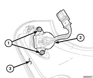
The recirculation door actuator (1) is a reversible, 12 volt direct current (DC), servo motor. The recirculation door actuator is located on the inboard side of the HVAC air inlet housing and is directly connected to the pivot shaft of the recirculation-air door.
The recirculation door actuator is interchangeable with the actuators for the blend-air door(s) and the mode-air doors. Each actuator is contained within an identical black molded plastic housing with an integral wire connector receptacle (2). Each actuator also has an identical output shaft with splines (3) that connect it to its door linkage and three integral mounting tabs (4) that allow the actuator to be secured to the air inlet housing. The recirculation door actuator does not require mechanical indexing to the recirculation-air door, as it is electronically calibrated by the A/C-heater control.
OPERATION
OPERATION
The recirculation door actuator is connected to the A/C-heater control through the vehicle electrical system by a dedicated two-wire lead and connector of the HVAC wire harness. The recirculation door actuator moves the recirculation-air door in two directions. When the A/C-heater control pulls the voltage on one side of the motor connection high and the other connection low, the recirculation-air door will move in one direction. When the A/C-heater control reverses the polarity of the voltage to the motor, the recirculation-air door moves in the opposite direction.
When the A/C-heater control makes the voltage to both connections high or low, the recirculation-air door stops and will not move.
The A/C-heater control uses a pulse-count positioning system to monitor the operation and relative position of the recirculation door actuator and the recirculation-air door. The A/C-heater control learns the recirculation-air door stop positions during the calibration procedure and stores a diagnostic trouble code (DTC) for any problems it detects in the recirculation door actuator circuits.
The recirculation door actuator is diagnosed using a scan tool. Refer to DIAGNOSTIC CODE INDEX .
The recirculation door actuator cannot be adjusted or repaired and must be replaced if inoperative or damaged.
REMOVAL
REMOVAL
Disable the airbag system before attempting any steering wheel,
steering column, or instrument panel component diagnosis or service.
Disconnect and isolate the negative battery (ground) cable, then wait
two minutes for the airbag system capacitor to discharge before
performing further diagnosis or service. This is the only sure way to
disable the airbag system. Failure to follow these instructions may
result in accidental airbag deployment and possible serious or fatal
injury.
WARNING:
Courtesy of CHRYSLER GROUP, LLC
- Disconnect and isolate the negative battery cable.
- Remove the right side instrument panel silencer panel. Refer to PANEL, SILENCER, REMOVAL .
- Remove the glove box and the glove box trim panel from the instrument panel. Refer to GLOVE BOX, INSTRUMENT PANEL, REMOVAL .
- Disconnect the HVAC wire harness connector (3) from the recirculation door actuator (1).
- Remove the two screws (4) that secure the recirculation door actuator to the air inlet housing (2) and remove the actuator.
INSTALLATION
INSTALLATION
Courtesy of CHRYSLER GROUP, LLC
- Position the recirculation door actuator (1) into the vehicle.
- Install the recirculation door actuator onto the HVAC air inlet
housing (2). If necessary, rotate the actuator slightly to align the
splines on the actuator output shaft (3) with those on the recirculation
door pivot shaft (4).
Fig. 15: Recirculation Door Actuator Removal/Installation
Courtesy of CHRYSLER GROUP, LLC - Install the two screws (4) that secure the recirculation door actuator (1) to the air inlet housing (2). Tighten the screws to 2 N.m (17 in. lbs.).
- Connect the HVAC wire harness connector (3) to the recirculation door actuator.
- Install the glove box trim panel and glove box. Refer to GLOVE BOX, INSTRUMENT PANEL, INSTALLATION .
- Install the right side instrument panel silencer. Refer to PANEL, SILENCER, INSTALLATION .
- Reconnect the negative battery cable.
- Initiate the Actuator Calibration function using a scan tool. Refer to STANDARD PROCEDURE .
CONTROL, A/C AND HEATER
DESCRIPTION
DESCRIPTION
Courtesy of CHRYSLER GROUP, LLC
The Automatic Temperature Control (ATC) heating and A/C system uses electrically operated controls. These controls provide the operator with a number of setting options to help control the climate and comfort within the vehicle.
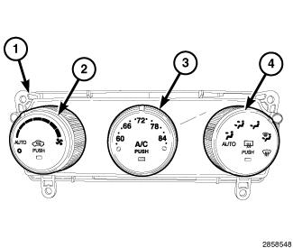
The A/C-heater control (1) for the ATC single zone system automatically maintains the interior comfort level desired by the operator. The ATC system automatically adjusts air temperature, airflow volume, airflow distribution and amount of inside air recirculation required to maintain occupant comfort, even under changing outside weather conditions. All controls are identified by International Standardization Organization (ISO) graphic symbols.
This ATC system offers several manual override features such as fan speed and airflow distribution. When the outside air contains smoke, odors, high humidity, or if rapid cooling is desired, the interior conditioned air can be recirculated within the vehicle.
The ATC A/C-heater control and integral computer is located in the instrument panel and contains:
- a rotary control for manual and automatic blower motor speed selection and for turning the heating and A/C system on and off (2). This control also contains a push button function for recirculating the conditioned air. The control contains an indicator lamp that illuminates when the system is in recirculation mode.
- a rotary control for temperature control of the discharged air (3). This control also contains a push button function for manually turning the A/C system on and off. The control contains an indicator lamp that illuminates when the A/C system is in operation.
- a rotary control for manual and automatic mode control of the discharged air (4). This control also contains a push button function for turning the rear window defogger system on and off. The control contains an indicator lamp that illuminates when the rear window defogger system is in operation.
The ATC A/C-heater control obtains vehicle speed, engine speed, engine coolant temperature, ambient air temperature and refrigerant system head pressure data and is diagnosed using a scan tool. Refer to DIAGNOSTIC CODE INDEX .
Prior to replacing the A/C-heater control, check for any Diagnostic Trouble Codes (DTCs) related to the heating and A/C system and run the Actuator Calibration function using a scan tool to verify that the concern is not an air door calibration issue. Refer to STANDARD PROCEDURE .
The A/C-heater control cannot be adjusted or repaired and must be replaced if inoperative or damaged.
REMOVAL
REMOVAL
Disable the airbag system before attempting any steering wheel,
steering column, or instrument panel component diagnosis or service.
Disconnect and isolate the negative battery (ground) cable, then wait
two minutes for the airbag system capacitor to discharge before
performing further diagnosis or service. This is the only sure way to
disable the airbag system. Failure to take the proper precautions could
result in accidental airbag deployment and possible serious or fatal
injury.
WARNING:
A/C-heater controls are NOT interchangeable between other vehicle
lines. If replacement of the A/C-heater control is required, only use
the control designed for the vehicle being serviced.
NOTE:
Take the proper precautions to protect the front face of the
instrument panel center bezel from cosmetic damage during this service
procedure.
NOTE:
Courtesy of CHRYSLER GROUP, LLC
- Disconnect and isolate the negative battery cable.
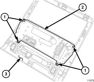
- Remove the center bezel (3) from the instrument panel and place it on a workbench. Refer to BEZEL, INSTRUMENT PANEL, CENTER, REMOVAL .
- Remove the four screws (1) that secure the A/C-heater control (2) to the instrument panel center bezel and remove the control.
INSTALLATION
INSTALLATION
Courtesy of CHRYSLER GROUP, LLC
- Position the A/C-heater control (2) into the instrument panel center bezel (3).
- Install the four screws (1) that secure the A/C-heater control to the instrument panel center bezel. Tighten the screws to 2 N.m (17 in. lbs.).
- Install the instrument panel center bezel. Refer to BEZEL, INSTRUMENT PANEL, CENTER, INSTALLATION
.
NOTE: The A/C-heater control automatically performs the Actuator Calibration function when the ignition is initially turned on when installing a new control or reinstalling the original control. However, the Actuator Calibration function must be manually initiated using a scan tool if the A/C-heater control has been previously installed in another vehicle.
- Reconnect the negative battery cable.
- Initiate the Actuator Calibration function using a scan tool. Refer to STANDARD PROCEDURE .
MODULE, POWER, BLOWER MOTOR
DESCRIPTION
DESCRIPTION
Courtesy of CHRYSLER GROUP, LLC
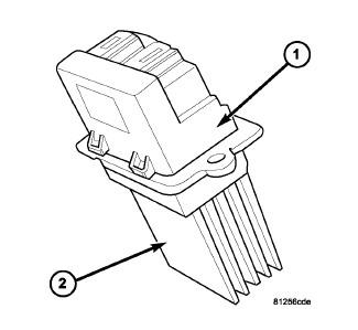
The standard Automatic Temperature Control (ATC) heating-A/C system on this model uses a blower motor power module to control blower motor speed.
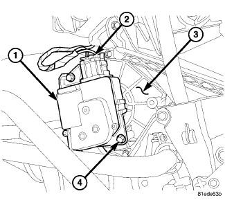
The blower motor power module is mounted to the rear of the HVAC housing, directly behind the glove box. The blower motor power module consists of a molded plastic mounting plate with two integral connector receptacles (1). Concealed behind the mounting plate is the power module electronic circuitry and a large finned heat sink (2).
The blower motor power module is accessed for service by removing the glove box.
OPERATION
OPERATION
The blower motor power module is connected to the vehicle electrical system through a dedicated lead and connector of the HVAC wire harness. A second connector receptacle receives the wire harness connector from the blower motor. The blower motor power module allows the microprocessor-based Automatic Temperature Control (ATC) A/C-heater control to calculate and provide infinitely variable blower motor speeds based upon either manual blower switch input or the ATC programming using a Pulse Width Modulated (PWM) circuit strategy.
The PWM voltage is applied to a comparator circuit that compares the PWM signal voltage to the blower motor feedback voltage. The resulting output drives the power module circuitry, which provides a linear output voltage to change or maintain the desired blower speed.
The blower motor power module is diagnosed using a scan tool. Refer to DIAGNOSTIC CODE INDEX .
The blower motor power module cannot be adjusted or repaired and must be replaced if inoperative or damaged.
REMOVAL
REMOVAL
Disable the airbag system before attempting any steering wheel,
steering column, or instrument panel component diagnosis or service.
Disconnect and isolate the negative battery (ground) cable, then wait
two minutes for the airbag system capacitor to discharge before
performing further diagnosis or service. This is the only sure way to
disable the airbag system. Failure to take the proper precautions may
result in accidental airbag deployment and possible serious or fatal
injury.
WARNING:
The heat sink for the blower motor power module may get very hot
during normal operation. If the blower motor was turned on prior to
servicing the blower motor power module, wait five minutes to allow the
heat sink to cool before performing diagnosis or service. Failure to
take this precaution may result in possible serious injury.
WARNING:
Courtesy of CHRYSLER GROUP, LLC
- Disconnect and isolate the negative battery cable.
- Remove the glove box from the instrument panel. Refer to GLOVE BOX, INSTRUMENT PANEL, REMOVAL .
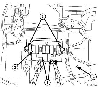
- Disconnect the two wire harness connectors (1) from the blower motor power module (2).
- Remove the two screws (3) that secure the blower motor power module to the HVAC housing (4) and remove the power module.
INSTALLATION
INSTALLATION
Courtesy of CHRYSLER GROUP, LLC
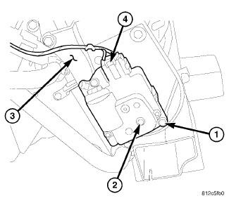
- Position the blower motor power module (2) into the HVAC housing (4).
- Install the two screws (3) that secure the blower motor power module to the HVAC housing. Tighten the screws to 2 N.m (17 in. lbs.).
- Connect the two wire harness connectors (1) to the blower motor power module.
- Install the glove box into the instrument panel. Refer to GLOVE BOX, INSTRUMENT PANEL, INSTALLATION .
- Reconnect the negative battery cable.
SENSOR, AMBIENT TEMPERATURE
DESCRIPTION
DESCRIPTION
Courtesy of CHRYSLER GROUP, LLC
The ambient air temperature sensor is a variable resistor that monitors the air temperature outside of the vehicle. The Automatic Temperature Control (ATC) heating and A/C system uses the ambient air temperature sensor data to help maintain optimum passenger compartment temperature levels. The ambient air temperature sensor is mounted to the front fascia.
OPERATION
OPERATION
The ambient air temperature sensor is a variable resistor that operates on a 5 volt Direct Current (DC) reference signal sent by the Totally Integrated Power Module (TIPM). The ambient air temperature sensor is connected to the TIPM through a two-wire lead and connector of the vehicle wire harness. The ambient air temperature sensor changes its internal resistance in response to changes in the outside air temperature, which either increases or decreases the reference signal voltage read by the TIPM. The TIPM converts and broadcasts the sensor data over the Controller Area Network (CAN) data bus, where it is read by the A/C-heater control, Powertrain Control Module (PCM) and other vehicle control modules.
The ambient air temperature sensor is diagnosed using a scan tool. Refer to DIAGNOSTIC CODE INDEX .
The ambient air temperature sensor cannot be adjusted or repaired and must be replaced if inoperative or damaged. Refer to SENSOR, AMBIENT TEMPERATURE, REMOVAL .
SENSOR, EVAPORATOR TEMPERATURE
DESCRIPTION
DESCRIPTION
Courtesy of CHRYSLER GROUP, LLC
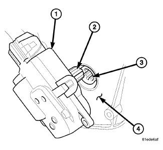
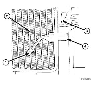
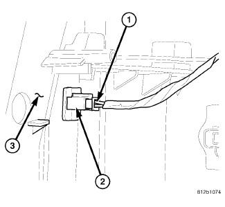
The evaporator temperature sensor (1) measures the temperature of the conditioned air downstream of the A/C evaporator (2). The evaporator temperature sensor is an electrical thermistor within a molded plastic case that is inserted into the HVAC housing (3) near the coldest point of the A/C evaporator. Two terminals within the connector receptacle (4) connect the sensor to the vehicle electrical system through a wire lead and connector of the HVAC wire harness.
The external location of the evaporator temperature sensor allows the sensor to be removed or installed without disturbing the refrigerant in the A/C system.
OPERATION
OPERATION
The evaporator temperature sensor monitors the temperature of the conditioned air downstream of the A/C evaporator and supplies an input signal to the A/C-heater control. The A/C-heater control uses the evaporator temperature sensor input signal to optimize A/C system performance and to protect the A/C system from evaporator freezing. The evaporator temperature sensor will change its internal resistance in response to the temperatures it monitors and is connected to the A/C-heater control through sensor ground circuit and a 5-volt reference signal circuit. As the temperature of the A/C evaporator decreases, the internal resistance of the evaporator temperature sensor decreases.
The A/C-heater control uses the monitored voltage reading as an indication of evaporator temperature. The A/C-heater control is programmed to respond to this input by requesting the powertrain control module (PCM) to cycle the A/C compressor clutch as necessary to optimize A/C system performance and to protect the A/C system from evaporator freezing.
The evaporator temperature sensor is diagnosed using a scan tool. Refer to DIAGNOSTIC CODE INDEX .
The evaporator temperature sensor cannot be adjusted or repaired and must be replaced if inoperative or damaged.
REMOVAL
REMOVAL
Disable the airbag system before attempting any steering wheel,
steering column or instrument panel component diagnosis or service.
Disconnect and isolate the negative battery (ground) cable and wait two
minutes for the airbag system capacitor to discharge before performing
further diagnosis or service. This is the only sure way to disable the
airbag system. Failure to follow these instructions may result in
accidental airbag deployment and possible serious or fatal injury.
WARNING:
Courtesy of CHRYSLER GROUP, LLC
- Disconnect and isolate the negative battery cable.
- Remove the glove box from the instrument panel. Refer to GLOVE BOX, INSTRUMENT PANEL, REMOVAL .
- Disconnect the HVAC wire harness connector (1) from the evaporator temperature sensor (2) located on the HVAC housing (3) and remove the sensor.
INSTALLATION
INSTALLATION
Courtesy of CHRYSLER GROUP, LLC
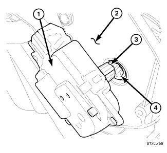
- Install the evaporator temperature sensor (2) into HVAC housing (3).
- Connect the HVAC wire harness connector (1) to the evaporator temperature sensor.
- Install the glove box into the instrument panel. Refer to GLOVE BOX, INSTRUMENT PANEL, INSTALLATION .
- Reconnect the negative battery cable.
SENSOR, SUN
DESCRIPTION
DESCRIPTION
Courtesy of CHRYSLER GROUP, LLC
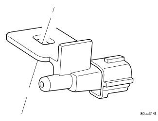
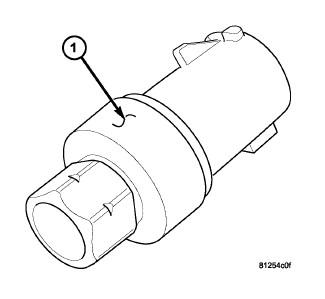
Typical sun sensor assembly shown in illustration.
NOTE:
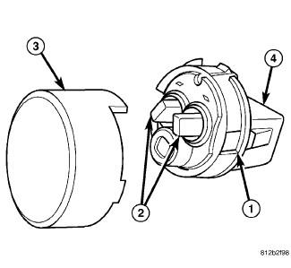
The Automatic Temperature Control (ATC) heating-A/C system uses a sun sensor assembly (1) to measure sun light intensity. The sun sensor assembly incorporates three sun sensors (2) within a molded plastic case with a clear lens (3), that protrudes through the center of the defroster grille. The wire harness receptacle (4) connects the sun sensors to the vehicle electrical system through a wire lead and connector of the instrument panel wire harness.
OPERATION
OPERATION
The Automatic Temperature Control (ATC) heating and A/C system uses two sun sensors to balance the system in response to side-to-side variations of sun light intensity. Passengers in sun and shadow require different functional settings because they experience very different temperatures. The sun sensor assembly provides data to the A/C-heater control to help determine proper mode and blend-air door positions and blower motor speeds. The sun sensors are not thermistor type sensors, but rather photo diodes. For this reason the sun sensors responds to sun light intensity rather than temperature. The sun sensor assembly is also used to sense day and night conditions for automatic headlight control, if equipped.
The sun sensor is diagnosed using a scan tool. Refer to DIAGNOSTIC CODE INDEX .
The sun sensor assembly cannot be adjusted or repaired and must be replaced if inoperative or damaged.
DIAGNOSIS AND TESTING
DIAGNOSIS AND TESTING - SUN SENSOR
Disable the airbag system before attempting any steering wheel,
steering column, or instrument panel component diagnosis or service.
Disconnect and isolate the negative battery (ground) cable. Wait two
minutes for the airbag system capacitor to discharge before performing
further diagnosis or service. This is the only sure way to disable the
airbag system. Failure to follow these instructions may result in
possible serious or fatal injury.
WARNING:
The sun sensor assembly is located so that the sun rays will hit the sensors in the same way that it will hit the driver and the passenger. It is important that the area in front of the sun sensor assembly be unobstructed. If the vehicle exhibits a lack of passenger comfort in sunny weather such as in the early afternoon, check for the following:
- Any items laying on top of the instrument panel are not covering the sun sensor.
- Any stickers on the windshield are not directly in front of the sun sensor.
- Confirm that the windshield wipers are properly adjusted.
- Confirm that the sun sensor is properly installed. Refer to SENSOR, SUN, INSTALLATION.
- Confirm that the defroster grille is properly installed. Refer to GRILLE, DEFROSTER, INSTALLATION .
The A/C heater module continually monitors the sun sensor circuits and will store Diagnostic Trouble Codes (DTCs) for any problem it detects. The sun sensor can be tested in the vehicle with a scan tool. Refer to DIAGNOSIS AND TESTING .
REMOVAL
REMOVAL
Disable the airbag system before attempting any steering wheel,
steering column, or instrument panel component diagnosis or service.
Disconnect and isolate the negative battery (ground) cable, then wait
two minutes for the airbag system capacitor to discharge before
performing further diagnosis or service. This is the only sure way to
disable the airbag system. Failure to take the proper precautions may
result in an accidental airbag deployment and possible serious or fatal
injury.
WARNING:

Courtesy of CHRYSLER GROUP, LLC
- Disconnect and isolate the negative battery cable.
- Using a small flat bladed tool, gently pry the sun sensor (1) out of the top of the instrument panel (3).
- Disconnect the wire harness connector (2) and remove the sensor.
INSTALLATION
INSTALLATION
Courtesy of CHRYSLER GROUP, LLC
- Position the sun sensor (1) near the instrument panel (3).
- Connect the wiring harness connector (2) to the sun sensor.
- Align the tab on the sun sensor with the slot in the opening of the instrument panel and gently push the sensor into the instrument panel. Make sure the sensor is fully engaged and lies flat in the instrument panel.
- Reconnect the negative battery cable.
SENSOR, TEMPERATURE, IN-CAR
DESCRIPTION
DESCRIPTION
Courtesy of CHRYSLER GROUP, LLC
The in-car temperature sensor (1) is used in the Automatic Temperature Control (ATC) heating and A/C system only. The in-car temperature sensor consists of an aspirator motor (2) and a temperature thermistor (3). The in-car temperature sensor sends a resistance signal to the ATC A/C heater module and is attached to the instrument panel, below the steering column.
OPERATION
OPERATION
Air is drawn from the passenger compartment by the aspirator motor and flows over the temperature thermistor. The thermistor changes resistance with air temperature. The Automatic Temperature Control (ATC) A/C-heater control receives the resistance signal over hard-wired circuits and calculates the temperature of the air in the passenger compartment. The ATC system then automatically makes adjustments to maintain the optimum passenger compartment comfort.
The in-car temperature sensor cannot be adjusted or repaired and must be replaced if inoperative or damaged.
DIAGNOSIS AND TESTING
DIAGNOSIS AND TESTING - IN-CAR TEMPERATURE SENSOR
For complete circuit diagrams, see Wiring Information. Wiring
Information includes wiring diagrams, connector pin-out and location
views, details of wire harness routing and retention, splice and ground
locations and proper wire and connector repair procedures.
NOTE:
Using a scan tool, check for Diagnostic Trouble Codes (DTCs) related to the in-car temperature sensor and the A/C-heater control. If any DTCs are found, repair as necessary. Refer to DIAGNOSIS AND TESTING . If no DTCs are found, perform the two following tests. Replace the in-car temperature sensor if the sensor fails either test.
ASPIRATOR MOTOR TEST
The in-car temperature sensor uses an aspirator motor to draw air from the passenger compartment and flow the air over the temperature thermistor. Test the motor as follows.
Courtesy of CHRYSLER GROUP, LLC
- Place the ignition in the Run position.
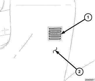
- Place a small piece of newspaper in front of the aspirator motor opening grille (1), located on the steering column opening cover (2). If the paper sticks to the grille, the aspirator motor is operating properly. The piece of paper should be only large enough to cover the opening.
- If the paper does not stick to the grille, check the in-car temperature sensor electrical connections and wiring. If connections and wiring are OK, replace the in-car temperature sensor.
TEMPERATURE THERMISTOR TEST
The in-car temperature sensor uses a temperature thermistor to provide resistance values that correlate with temperature change. Test the thermistor as follows.
- Remove the in-car temperature sensor and place it on a workbench. Refer to SENSOR, TEMPERATURE, IN-CAR, REMOVAL.
- Note the current ambient air temperature of the work area.
- Use an ohm meter and check the resistance between pins 1 and 2 of the in-car temperature sensor. Compare the temperature of the work area to the found resistance value. The resistance should be within specifications as listed in the Resistance and Temperature chart. If not OK, replace the in-car temperature sensor.
RESISTANCE AND TEMPERATURE
Air Temperature Range
Low Resistance Range (kohm)
High Resistance Range (kohm)
-21° to -15°C (-5° to 5°F)
292 ± 1.0
223 ± 0.9
-14° to -9°C (6° to 15°F)
198 ± 0.9
161 ± 0.8
-8° to -4°C (16° to 25°F)
144 ± 0.8
123 ± 0.8
-3° to 1°C (26° to 35°F)
111 ± 0.7
95 ± 0.7
2 to 7°C (36° to 45°F)
86 ± 0.7
70 ± 0.6
8 to 12°C (46° to 55°F)
64 ± 0.6
55 ± 0.5
13° to 18°C (56° to 65°F)
51 ± 0.5
42 ± 0.4
19° to 23°C (66° to 75°F)
39 ± 0.4
33 ± 0.3
24° to 29°C (76° to 85°F)
31 ± 0.3
26 ± 0.3
30° to 35°C (86° to 95°F)
24 ± 0.3
20 ± 0.3
36° to 40°C (96° to 105°F)
18 ± 0.3
16 ± 0.3
41° to 46°C (106° to 115°F)
15 ± 0.3
13 ± 0.3
REMOVAL
REMOVAL
Disable the airbag system before attempting any steering wheel,
steering column or instrument panel component diagnosis or service.
Disconnect and isolate the negative battery (ground) cable, then wait
two minutes for the airbag system capacitor to discharge before
performing further diagnosis or service. This is the only sure way to
disable the airbag system. Failure to follow these instructions may
result in accidental airbag deployment and possible serious or fatal
injury.
WARNING:
Take the proper precautions to protect the face of the steering
column opening cover from cosmetic damage while performing this
procedure.
NOTE:
Courtesy of CHRYSLER GROUP, LLC
- Disconnect and isolate the negative battery cable.
- Remove the steering column opening cover (3) and place it on a workbench.
- Remove the two screws (1) that secure the in-car temperature sensor (2) to the steering column opening cover and remove the sensor.
INSTALLATION
INSTALLATION
Take the proper precautions to protect the face of the steering
column opening cover from cosmetic damage while performing this
procedure.
NOTE:
Courtesy of CHRYSLER GROUP, LLC
- Position the in-car temperature sensor (2) onto the steering column opening cover (3).
- Install the two screws (1) that secure the in-car temperature sensor to the steering column opening cover. Tighten the screws securely.
- Install the steering column opening cover.
- Reconnect the negative battery cable.
TRANSDUCER, A/C PRESSURE
DESCRIPTION
DESCRIPTION
Courtesy of CHRYSLER GROUP, LLC
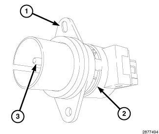
The A/C pressure transducer (1) is a switch that is installed on a fitting located on the A/C liquid line. An internally threaded fitting on the A/C pressure transducer connects it to the externally threaded Schrader-type fitting on the A/C liquid line. A rubber O-ring seals the connection between the A/C pressure transducer and the liquid line fitting. The A/C pressure transducer is connected to the vehicle electrical system by a molded plastic connector with three terminals.
OPERATION
OPERATION
The A/C pressure transducer monitors the pressures in the high side of the refrigerant system through its connection to a fitting on the A/C liquid line. The A/C pressure transducer will change its internal resistance in response to the pressures it monitors. A Schrader-type valve in the liquid line fitting permits the A/C pressure transducer to be removed or installed without disturbing the refrigerant in the A/C system.
The totally integrated power module (TIPM) provides a five volt reference signal and a sensor ground to the A/C pressure transducer. The powertrain control module (PCM) monitors the output voltage of the A/C pressure transducer on the CAN B bus to determine refrigerant pressure. The PCM is programmed to respond to the A/C pressure transducer and other sensor inputs and control the operation of the A/C compressor clutch and the radiator cooling fan to help optimize A/C system performance and to protect the system components from damage. The PCM will disengage the A/C compressor clutch when high side pressure rises above 3082 kPa (447 psi) and re-engage the clutch when high side pressure drops below 2937 kPa (426 psi). The A/C pressure transducer will also disengage the A/C compressor clutch if the high side pressure drops below 110 kPa (16 psi) and will re-engage the clutch when the high side pressure rises above 221 kPa (32 psi). If the refrigerant pressure rises above 1655 kPa (240 psi), the PCM will actuate the cooling fan. The A/C pressure transducer input to the PCM will also prevent the A/C compressor clutch from engaging when ambient temperatures are below about 4.5° C (40° F) due to the pressure/temperature relationship of the refrigerant.
The A/C pressure transducer is tested using a scan tool. Refer to the DIAGNOSTIC CODE INDEX .
The A/C pressure transducer cannot be adjusted or repaired and must be replaced if inoperative or damaged.
REMOVAL
REMOVAL
It is not necessary to discharge the refrigerant system to replace the A/C pressure transducer.
NOTE:
- Disconnect and isolate the negative battery cable.
Fig. 34: Internal Heat Exchanger, Pressure Transducer & Harness Connector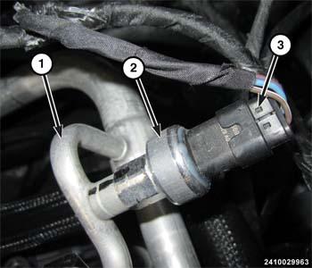
Courtesy of CHRYSLER GROUP, LLC - Disconnect the wire harness connector (3) from the A/C pressure transducer (2).
- Remove the A/C pressure transducer from the Internal Heat Exchanger (1) and remove and discard the O-ring seal.
INSTALLATION
INSTALLATION
Use only the specified O-ring as it is made of special material for
this system. Use only refrigerant oil of the type required for the A/C
compressor.
NOTE:
- Lubricate a new rubber O-ring seal with clean refrigerant oil and install it onto the liquid line fitting.
- Install the A/C pressure transducer (2) onto the Internal Heat Exchanger (1) and tighten the A/C pressure transducer securely.
- Connect the wire harness connector (3) to the A/C pressure transducer.
- Connect the negative battery cable.
Courtesy of CHRYSLER GROUP, LLC
DISTRIBUTION
DUCT, DEFROSTER
REMOVAL
REMOVAL
Disable the airbag system before attempting any steering wheel,
steering column, or instrument panel component diagnosis or service.
Disconnect and isolate the battery negative (ground) cable, then wait
two minutes for the airbag system capacitor to discharge before
performing further diagnosis or service. This is the only sure way to
disable the airbag system. Failure to take the proper precautions could
result in accidental airbag deployment and possible serious or fatal
injury.
WARNING:
Take the proper precautions to protect the front face of the instrument panel from cosmetic damage.
NOTE:
Courtesy of CHRYSLER GROUP, LLC
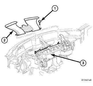
- Remove the instrument panel and place it on a workbench. Refer to PANEL, INSTRUMENT, REMOVAL .
- Remove the four screws (1) that secure the defroster duct (2) to the top of the HVAC air distribution housing (3) and remove the duct.
INSTALLATION
INSTALLATION
Courtesy of CHRYSLER GROUP, LLC
- Position the defroster duct (2) onto the top of the HVAC air distribution housing (3).
- Install the four screws (1) that secure the defroster duct to the air distribution housing. Tighten the screws to 2 N.m (17 in. lbs.).
- Install the instrument panel. Refer to PANEL, INSTRUMENT, INSTALLATION .
DUCT, FLOOR CONSOLE
REMOVAL
REMOVAL
Courtesy of CHRYSLER GROUP, LLC
- Remove the center floor console. Refer to CONSOLE, FLOOR, REMOVAL .
- Remove the retainer (3) that secures the floor console duct (2) to the center floor panel (4).
- Disconnect the floor console duct from the floor distribution duct (1) and remove the console duct from the vehicle.
INSTALLATION
INSTALLATION
Courtesy of CHRYSLER GROUP, LLC
- Position the floor console duct (2) into the vehicle.
- Connect the floor console duct to the floor distribution duct (1).
- Install the retainer (3) that secures the floor console duct to the center floor panel (4).
- Install the center floor console. Refer to CONSOLE, FLOOR, INSTALLATION .
DUCT, FLOOR DISTRIBUTION
REMOVAL
REMOVAL
Disable the airbag system before attempting any steering wheel,
steering column or instrument panel component diagnosis or service.
Disconnect and isolate the negative battery (ground) cable and wait two
minutes for the airbag system capacitor to discharge before performing
further diagnosis or service. This is the only sure way to disable the
airbag system. Failure to follow these instructions may result in
accidental airbag deployment and possible serious or fatal injury.
WARNING:
Take the proper precautions to protect the front face of the instrument panel from cosmetic damage.
NOTE:
INTERMEDIATE FLOOR DISTRIBUTION DUCTS
Courtesy of CHRYSLER GROUP, LLC
- Remove the center floor console. Refer to CONSOLE, FLOOR, REMOVAL .
- Remove the front seats. Refer to SEAT, FRONT, REMOVAL .
- Roll back the front floor carpet from under the instrument panel toward the rear of the vehicle. Refer to WARNING .
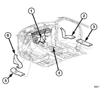
- Disengage the passenger side front intermediate floor distribution duct (2) from the stud located on the passenger side of the floor support (4).
- Disconnect the passenger side front intermediate floor distribution duct from the front floor distribution duct (1).
- Disconnect the passenger side front intermediate floor distribution duct from the passenger side rear intermediate floor distribution duct (3).
- Remove the passenger side rear intermediate floor distribution duct from the floor support.
- Disengage the driver side rear intermediate floor distribution duct (5) from the stud located on the driver side of the floor support.
- Disconnect the driver side front intermediate floor distribution duct (6) from the front floor distribution duct.
- Disconnect the driver side front intermediate floor distribution duct from the driver side rear intermediate floor distribution duct.
- Remove the driver side rear intermediate floor distribution duct from the floor support.
FRONT FLOOR DISTRIBUTION DUCT
Courtesy of CHRYSLER GROUP, LLC
- Remove the HVAC air distribution housing. Refer to HOUSING, HVAC, REMOVAL.
- Remove the six screws (1) that secure the front floor distribution duct (2) to the bottom of the air distribution housing (3) and remove the duct.
INSTALLATION
INSTALLATION
INTERMEDIATE FLOOR DISTRIBUTION DUCTS
Courtesy of CHRYSLER GROUP, LLC
- Install the driver side rear intermediate floor distribution duct (5) and the passenger side rear intermediate floor distribution duct (3) into the slots in the floor support (4).
- Connect the driver side front intermediate floor distribution duct (6) to the driver side rear intermediate floor distribution duct.
- Connect the driver side front intermediate floor distribution duct to the front floor distribution duct (1).
- Engage the driver side rear intermediate floor distribution duct to the stud located on the driver side of the floor support.
- Connect the passenger side front intermediate floor distribution duct (2) to the passenger side rear intermediate floor distribution duct.
- Connect the passenger side front intermediate floor distribution duct to the front floor distribution duct.
- Engage the passenger side front intermediate floor distribution duct to the stud located on the passenger side of the floor support.
- Install the carpet onto the front floor panel and under the instrument panel. Refer to WARNING .
- Install the front seats. Refer to SEAT, FRONT, INSTALLATION .
- Install the center floor console. Refer to CONSOLE, FLOOR, INSTALLATION .
FRONT FLOOR DISTRIBUTION DUCT
Courtesy of CHRYSLER GROUP, LLC
- Position the front floor distribution duct (2) to the bottom of the HVAC air distribution housing (3).
- Install the six screws (1) that secure the front floor distribution duct to the air distribution housing. Tighten the screws to 2 N.m (17 in. lbs.).
- Install the air distribution housing. Refer to DUCT, FLOOR DISTRIBUTION, INSTALLATION.
DUCT, INSTRUMENT PANEL
REMOVAL
REMOVAL
Disable the airbag system before attempting any steering wheel,
steering column, or instrument panel component diagnosis or service.
Disconnect and isolate the battery negative (ground) cable, then wait
two minutes for the airbag system capacitor to discharge before
performing further diagnosis or service. This is the only sure way to
disable the airbag system. Failure to take the proper precautions could
result in accidental airbag deployment and possible serious or fatal
injury.
WARNING:
Take the proper precautions to protect the front face of the instrument panel from cosmetic damage.
NOTE:
Courtesy of CHRYSLER GROUP, LLC
- Remove the instrument panel and place it on a workbench. Refer to PANEL, INSTRUMENT, REMOVAL .
- Remove the screw that secures the instrument panel top pad (1) to the reinforcement bracket (2).
- Remove the four screws that secure the driver side instrument panel duct and demister duct assembly (3) to the instrument panel and remove the duct assembly.
- Remove the four screws that secure the passenger side instrument panel duct and demister duct assembly (4) to the instrument panel and remove the duct assembly.
INSTALLATION
INSTALLATION
Courtesy of CHRYSLER GROUP, LLC
- Position the passenger side instrument panel duct and demister duct assembly (4) into the instrument panel.
- Install the passenger side instrument panel duct and demister duct assembly onto the outlets of the instrument panel. Make sure that the ducts are correctly installed over the instrument panel and demister outlet seals.
- Install the four screws that secure the passenger side instrument panel duct and demister duct assembly to the instrument panel. Tighten the screws to 2.2 N.m (20 in. lbs.).
- Position the driver side instrument panel duct and demister duct assembly (3) into the instrument panel.
- Install the driver side instrument panel duct and demister duct assembly onto the outlets of the instrument panel. Make sure that the ducts are correctly installed over the instrument panel and demister outlet seals.
- Install the four screws that secure the driver side instrument panel duct and demister duct assembly to the instrument panel. Tighten the screws to 2.2 N.m (20 in. lbs.).
- Install the screw that secures the instrument panel top pad (1) to the reinforcement bracket (2). Tighten the screw to 2.2 N.m (20 in. lbs.).
- Install the instrument panel. Refer to PANEL, INSTRUMENT, INSTALLATION .
DUCT, INSTRUMENT PANEL DEMISTER
REMOVAL
REMOVAL
Disable the airbag system before attempting any steering wheel,
steering column, or instrument panel component diagnosis or service.
Disconnect and isolate the battery negative (ground) cable, then wait
two minutes for the airbag system capacitor to discharge before
performing further diagnosis or service. This is the only sure way to
disable the airbag system. Failure to take the proper precautions could
result in accidental airbag deployment and possible serious or fatal
injury.
WARNING:
Take the proper precautions to protect the front face of the instrument panel from cosmetic damage.
NOTE:
Courtesy of CHRYSLER GROUP, LLC
- Remove the instrument panel and place it on a workbench. Refer to PANEL, INSTRUMENT, REMOVAL .
- Remove the screw that secures the instrument panel top pad (1) to the reinforcement bracket (2).
- Remove the four screws that secure the driver side instrument panel duct and demister duct assembly (3) to the instrument panel and remove the duct assembly.
- Remove the four screws that secure the passenger side instrument panel duct and demister duct assembly (4) to the instrument panel and remove the duct assembly.
INSTALLATION
INSTALLATION
Courtesy of CHRYSLER GROUP, LLC
- Position the passenger side instrument panel duct and demister duct assembly (4) into the instrument panel.
- Install the passenger side instrument panel duct and demister duct assembly onto the outlets of the instrument panel. Make sure that the ducts are correctly installed over the instrument panel and demister outlet seals.
- Install the four screws that secure the passenger side instrument panel duct and demister duct assembly to the instrument panel. Tighten the screws to 2.2 N.m (20 in. lbs.).
- Position the driver side instrument panel duct and demister duct assembly (3) into the instrument panel.
- Install the driver side instrument panel duct and demister duct assembly onto the outlets of the instrument panel. Make sure that the ducts are correctly installed over the instrument panel and demister outlet seals.
- Install the four screws that secure the driver side instrument panel duct and demister duct assembly to the instrument panel. Tighten the screws to 2.2 N.m (20 in. lbs.).
- Install the screw that secures the instrument panel top pad (1) to the reinforcement bracket (2). Tighten the screw to 2.2 N.m (20 in. lbs.).
- Install the instrument panel. Refer to PANEL, INSTRUMENT, INSTALLATION .
FILTER, CABIN AIR
DESCRIPTION
DESCRIPTION
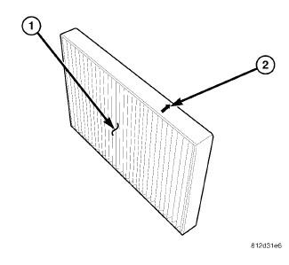
Courtesy of CHRYSLER GROUP, LLC
All models are equipped with a cabin air filter (1) that helps purify the outside air entering the HVAC housing. The filter is mounted in the engine compartment, inside of the fresh air inlet housing of the heating-A/C system.
The filter should be replaced at least every 24, 000 km (15, 000 miles) or each year and checked if heating-A/C system performance seems lower than expected. The cabin air filter is labeled with "REAR OF VEHICLE" and an arrow (2) to indicate air flow direction through the filter.
REMOVAL
REMOVAL
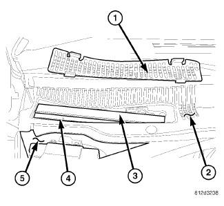
Courtesy of CHRYSLER GROUP, LLC
- Remove the air inlet grille (1) from the wiper module screen (2) located near the dash panel in the engine compartment.
- Open the filter door (3) on the top of the cabin air filter housing (4) located inside of the dash panel plenum (5).
Fig. 50: Removing/Installing Particulate Air Filter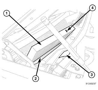
Courtesy of CHRYSLER GROUP, LLCNOTE: To aid in reinstallation, note the installed position of the cabin air filter prior to removal of the filter.
- Remove the cabin air filter (1) from the cabin air filter housing (2) located inside of the dash panel plenum (3). Note the direction of air flow indicated by an arrow (4) on the filter.
INSTALLATION
INSTALLATION
The cabin air filter is labeled with "REAR OF VEHICLE" and an arrow
to indicate air flow direction through the filter. Make sure to properly
install the cabin air filter. Failure to properly install the filter
will result in the need to replace the filter sooner than required by
design.
NOTE:
Courtesy of CHRYSLER GROUP, LLC
- Install the cabin air filter (1) into the cabin air filter housing
(2) located inside of the dash panel plenum (3). Insert the cabin air
filter down directly into the filter housing with the arrow (4) on the
filter pointing to the rear of the vehicle. The cabin air filter is held
in place by friction between the filter element and the filter housing,
so no fasteners are required.
Fig. 52: Removing/Installing Particulate Air Filter
Courtesy of CHRYSLER GROUP, LLC - Close the filter door (3) on the top of the cabin air filter housing (4) located inside of the dash panel plenum (5).
- Install the air inlet grille (1) onto the wiper module screen (2).
HOUSING, HVAC
REMOVAL
HOUSING-AIR DISTRIBUTION
Review the warnings and cautions for this system before performing
the procedure. Failure to follow these instructions may result in
serious injury or death.
WARNING:
Disable the airbag system before attempting any steering wheel,
steering column or instrument panel component diagnosis or service.
Disconnect and isolate the negative battery (ground) cable and wait two
minutes for the airbag system capacitor to discharge before performing
further diagnosis or service. This is the only sure way to disable the
airbag system. Failure to follow these instructions may result in
accidental airbag deployment and possible serious or fatal injury.
WARNING:
The heater core tubes are not serviced separately from the heater
core. The heater core tubes should not be repositioned, loosened or
removed from the heater core. Failure to follow these instructions may
result in a coolant leak and possible serious or fatal injury.
WARNING:
The air distribution housing must be removed from the HVAC housing
and disassembled for service of the mode-air and blend-air doors.
NOTE:
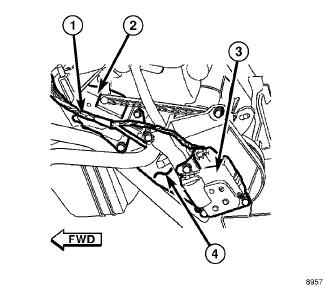
Courtesy of CHRYSLER GROUP, LLC
- Remove the HVAC housing assembly and place it on a suitable workbench. Refer to HOUSING, HVAC, REMOVAL.
- Disconnect the HVAC wire harness (1) from the mode door actuator (2)
and the blend door actuator (3) located on the driver side of the air
distribution housing (4).
Fig. 54: Heater Core Removal & Installation
Courtesy of CHRYSLER GROUP, LLC - Remove the blend door actuator (1) from the driver side of the air distribution housing (2). Refer to ACTUATOR, BLEND DOOR, REMOVAL.
- Remove the two screws (8) that secure the flange (7) to the front of the HVAC housing (9) and remove the flange.
- Remove the screw (5) that secures the heater core retaining bracket (3) to the driver side of the air distribution housing and remove the bracket.
- Disengage the heater core tubes (6) from the foam seal at the front
of the HVAC housing and carefully pull the heater core (4) straight out
of the side of the air distribution housing.
Fig. 55: Removing Air Distribution Housing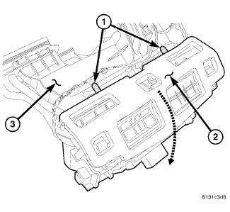
Courtesy of CHRYSLER GROUP, LLC - Remove the two screws (1) that secure the air distribution housing (2) to the rear of the HVAC housing (3).
- Tilt the top of the air distribution housing rearward to disconnect the distribution housing from the tab-and-slot type retainers located at the bottom of the housing.
- Disconnect the air distribution housing from rear floor distribution ducts.
- Remove the air distribution housing from the vehicle.
- If required, disassemble the air distribution housing. Refer to HOUSING, HVAC, DISASSEMBLY.
HOUSING-AIR INLET
Disable the airbag system before attempting any steering wheel,
steering column, or instrument panel component diagnosis or service.
Disconnect and isolate the negative battery (ground) cable, then wait
two minutes for the airbag system capacitor to discharge before
performing further diagnosis or service. This is the only sure way to
disable the airbag system. Failure to take the proper precautions could
result in accidental airbag deployment and possible serious or fatal
injury.
WARNING:
The air inlet housing must be removed from HVAC housing and disassembled for service of the recirculation-air door.
NOTE:
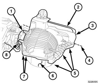
Courtesy of CHRYSLER GROUP, LLC
- Remove the HVAC housing assembly and place it on a workbench. Refer to HOUSING, HVAC, REMOVAL.
- Disconnect the HVAC wire harness connector (8) from the recirculation door actuator (1).
- Carefully cut the foam seal (2) along the parting line (4) of the air inlet housing (3). If the seal is deformed or damaged, it must be replaced.
- Remove the five screws (5 and 7) that secure the air inlet housing to HVAC housing (6).
- Remove the air inlet housing from the HVAC housing.
- If required, disassemble the air inlet housing. Refer to HOUSING, HVAC, DISASSEMBLY.
HOUSING-FRESH AIR INLET
The fresh air inlet housing must be removed from the vehicle for removal of the HVAC housing.
NOTE:
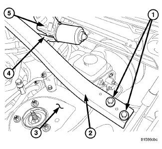
Courtesy of CHRYSLER GROUP, LLC
- Disconnect and isolate the negative battery cable.
- Remove the cowl top panel from the dash panel. Refer to COVER, COWL PANEL, REMOVAL .
- Remove the two bolts (1) that secure the strut support (2) to the driver side strut tower (3).
- Disengage the wiper motor (5) from the bracket (4) located on the strut support.
Fig. 58: Strut Support- Passenger Side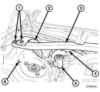
Courtesy of CHRYSLER GROUP, LLC - Disengage the retainer that secures the wire harness (4) to the bottom of the strut support (3).
- Remove the purge solenoid (5) from its mounting bracket and position the solenoid out of the way.
- Remove the two bolts (1) that secure the strut support to the passenger side strut tower (6) and remove the support from the engine compartment.
- Position the powertrain control module (PCM) out of the way.
Fig. 59: Push Pins-Fresh Air Inlet Housing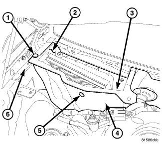
Courtesy of CHRYSLER GROUP, LLC - Remove the push-pin retainer (1) that secures the fresh air inlet housing (2) to the passenger side inner fender (6).
- Disengage the wire harness retainer (3) from inside the bottom of the fresh air inlet housing, if equipped.
- Remove the push-pin retainer (5) that secures the insulator (4) to
the front of the fresh air inlet housing and position the insulator out
of the way.
Fig. 60: Fresh Air Inlet Housing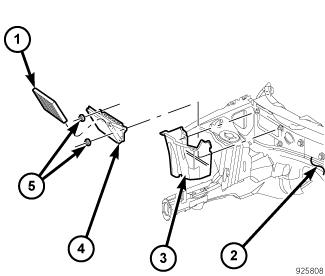
Courtesy of CHRYSLER GROUP, LLC - Remove the two nuts (5) that secure the fresh air inlet housing (3), cabin air filter (1) and filter housing (4) to the dash panel (2).
- Remove the fresh air inlet housing, cabin air filter and filter housing as an assembly from the dash panel.
HOUSING-HVAC ASSEMBLY
Disable the airbag system before attempting any steering wheel,
steering column or instrument panel component diagnosis or service.
Disconnect and isolate the negative battery (ground) cable and wait two
minutes for the airbag system capacitor to discharge before performing
further diagnosis or service. This is the only sure way to disable the
airbag system. Failure to follow these instructions may result in
accidental airbag deployment and possible serious or fatal injury.
WARNING:
Disable the airbag system before attempting any steering wheel,
steering column, or instrument panel component diagnosis or service.
Disconnect and isolate the negative battery (ground) cable, then wait
two minutes for the airbag system capacitor to discharge before
performing further diagnosis or service. This is the only sure way to
disable the airbag system. Failure to take the proper precautions could
result in accidental airbag deployment and possible serious or fatal
injury.
WARNING:
The HVAC housing must be removed from the vehicle and disassembled for service of the A/C evaporator.
NOTE:
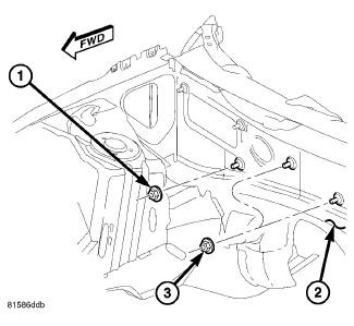
Courtesy of CHRYSLER GROUP, LLC
- Recover the refrigerant from the refrigerant system. Refer to PLUMBING, STANDARD PROCEDURE.
- Drain the engine cooling system. Refer to STANDARD PROCEDURE .
- Disconnect and isolate the negative battery cable.
- Remove the fresh air inlet housing from the dash panel. Refer to HOUSING, HVAC, REMOVAL.
- Disconnect the A/C liquid line and the A/C suction line from the A/C evaporator. Refer to LINE, A/C LIQUID, REMOVAL.
- Disconnect the heater hoses from the heater core tubes.
- Remove the three nuts (1 and 3) that secure the HVAC housing to the engine compartment side of the dash panel (2).
Fig. 62: Housing-HVAC-Interior Removal & Installation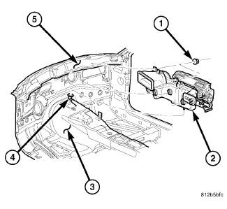
Courtesy of CHRYSLER GROUP, LLC - Remove the instrument panel from the passenger compartment. Refer to PANEL, INSTRUMENT, REMOVAL .
- Disconnect the floor console duct. Refer to DUCT, FLOOR CONSOLE, REMOVAL.
- Disconnect the rear floor distribution ducts. Refer to DUCT, FLOOR DISTRIBUTION, REMOVAL.
- Remove the defroster ducts. Refer to DUCT, DEFROSTER, REMOVAL.
- Remove the two nuts (1) that secure the HVAC housing (2) to the passenger compartment side of the dash panel (5).
- Pull the HVAC housing assembly rearward so that the mounting studs clear the dash panel.
- Lift the HVAC housing assembly upwards so that the condensate drain tube clears the grommet (4) in the floor panel (3) and remove the HVAC housing assembly from the passenger compartment.
- If required, disassemble the HVAC housing assembly. Refer to HOUSING, HVAC, DISASSEMBLY.
DISASSEMBLY
HOUSING-AIR DISTRIBUTION
The air distribution housing must be removed from the HVAC housing
and disassembled for service of the mode-air and blend-air doors.
NOTE:

Courtesy of CHRYSLER GROUP, LLC
- Remove the air distribution housing (1) from the HVAC housing and place it on a workbench. Refer to HOUSING, HVAC, REMOVAL.
- Remove the screws (2) that secure the mode door actuator (4) and the blend door actuator (7) to the driver side of the air distribution housing and remove the actuators.
- Remove the screws (5) that secure the blend door actuator mounting
bracket (6) and the mode door actuator mounting bracket (3) to the
driver side of the air distribution housing and remove the mounting
brackets.
Fig. 64: Removing/Installing LH Actuator Linkages Air Housing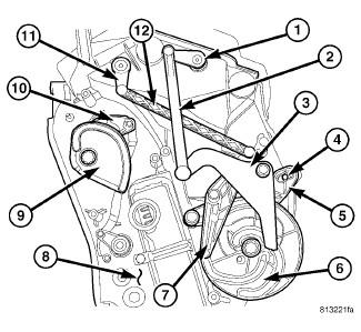
Courtesy of CHRYSLER GROUP, LLC - Remove the instrument panel door linkage (3) from the pivot shaft located on the driver side of the air distribution housing (8) and carefully disconnect the linkage rod (2) from the instrument panel door lever (1).
- Remove the defrost/demister door linkage (7) from the pivot shaft on the air distribution housing and carefully disconnect the linkage rod (12) from the defrost/demister door lever (11).
- Remove the mode door cam (6) from the air distribution housing.
- Remove the floor door linkage (5) from the floor door lever (4) and the air distribution housing.
- Remove the blend door cam (9) from the blend door lever (10) and the air distribution housing.
Fig. 65: Duct-Front Floor Distribution
Courtesy of CHRYSLER GROUP, LLC - Remove the six screws (1) that secure the front floor distribution
duct (2) to the bottom of the air distribution housing (3) and remove
the duct.
Fig. 66: Removing/Installing Air Housing-Seal & Screws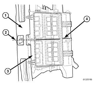
Courtesy of CHRYSLER GROUP, LLC - Carefully cut the foam seal (1) along the parting line (2) of the two halves of the air distribution housing (3). If the seal is deformed or damaged, it must be replaced.
- Remove the screws (4) that secure the two halves of the air distribution housing together.
Fig. 67: Removing/Installing Partition Air Housing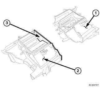
Courtesy of CHRYSLER GROUP, LLC - Carefully separate the left half of the air distribution housing (1) from the right half of the housing (2).
- Remove the center partition (3).
Fig. 68: Removing Air Doors From Air Housing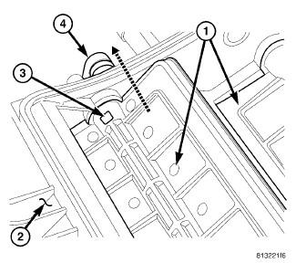
Courtesy of CHRYSLER GROUP, LLC - To remove the air doors (1) from the air distribution housing (2),
first carefully push down on the tab (3) of the air door lever (4)
located in the pivot shaft of the air door being removed.
NOTE: If the seal on the air door is deformed or damaged, the air door must be replaced.
- Gently pull the air door lever out of the pivot shaft and remove the air door(s) from the air distribution housing as required.
HOUSING-AIR INLET
The air inlet housing must be removed from HVAC housing and disassembled for service of the recirculation-air door.
NOTE:
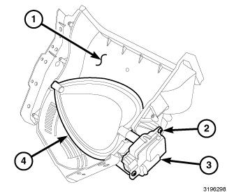
Courtesy of CHRYSLER GROUP, LLC
- Remove the air inlet housing (1) from the HVAC housing and place it on a workbench. Refer to HOUSING, HVAC, REMOVAL.
- Remove the two screws (2) that secure the recirculation door actuator (3) to the air inlet housing and remove the actuator.
- Remove the recirculation-air door (4) from the air inlet housing.
HOUSING-HVAC
The HVAC housing must be removed from the vehicle and disassembled for service of the A/C evaporator.
NOTE:
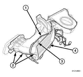
Courtesy of CHRYSLER GROUP, LLC
- Remove the HVAC housing assembly and place it on a workbench. Refer to HOUSING, HVAC, REMOVAL.
- Remove the air inlet housing. Refer to HOUSING, HVAC, REMOVAL.
- Remove the air distribution housing. Refer to HOUSING, HVAC, REMOVAL.
- Remove the blower motor. Refer to MOTOR, BLOWER, REMOVAL.
- Remove the blower motor power module. Refer to MODULE, POWER, BLOWER MOTOR, REMOVAL.
- Remove the evaporator temperature sensor. Refer to SENSOR, EVAPORATOR TEMPERATURE, REMOVAL.
- Remove the HVAC wiring harness (1).
- Remove the ten screws (2) that secure the upper half of the HVAC
housing (3) to the lower half of the HVAC housing (4) and remove the
upper housing.
Fig. 71: Removing/Installing A/C Evaporator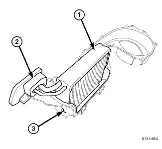
Courtesy of CHRYSLER GROUP, LLC - Carefully lift the A/C evaporator (1) and foam seal (2) out of the lower half of the HVAC housing (3).
NOTE: If the foam seal at the front of the HVAC housing is deformed or damaged, the seal must be replaced.
- If required, remove the A/C expansion valve, tapping block and foam seal from the A/C evaporator. Refer to VALVE, A/C EXPANSION, REMOVAL.
ASSEMBLY
HOUSING-AIR DISTRIBUTION
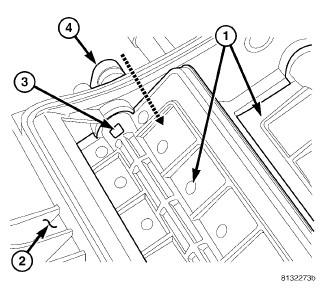
Courtesy of CHRYSLER GROUP, LLC
- Install the air doors (1) into the air distribution housing (2) as required. Align the air door with the pivot shaft hole in the housing.
- Align and install the air door lever (4) into the pivot shaft of the
air door. Make sure that the tab (3) on the door lever is securely
engaged to the pivot shaft.
Fig. 73: Removing/Installing Partition Air Housing
Courtesy of CHRYSLER GROUP, LLC - Align the air door pivot shafts with the pivot holes in the center partition (3) and install the partition onto the left half of the air distribution housing (1).
- Align the air door pivot shafts to each other and carefully install
the left half of the air distribution housing to the right half of the
housing (2).
Fig. 74: Removing/Installing Air Housing-Seal & Screws
Courtesy of CHRYSLER GROUP, LLC - Install the screws (4) that secure the two halves of the air distribution housing (3) together. Tighten the screws to 2.2 N.m (20 in. lbs.).
- Inspect the foam seal (1), especially at the parting line (2). If the seal is deformed or damaged, it must be replaced.
Fig. 75: Duct-Front Floor Distribution
Courtesy of CHRYSLER GROUP, LLC - Position the front floor distribution duct (2) onto the air distribution housing (3).
- Install the six screws (1) that secure the front floor distribution
duct to the air distribution housing. Tighten the screws to 2 N.m (17
in. lbs.).
Fig. 76: Removing/Installing LH Actuator Linkages Air Housing
Courtesy of CHRYSLER GROUP, LLC - Install the blend door cam (9) onto the blend door lever (10) and to the pivot shaft located on the driver side of the air distribution housing (8).
- Install the floor door linkage (5) onto the floor door lever (4) and to the pivot shaft.
NOTE: Align the guide pin on the floor door linkage with the guides on the mode door cam during installation of the floor door linkage.
- Install the mode door cam (6) onto the pivot shaft.
- Connect the defrost/demister door linkage rod (12) to the defrost/demister door lever (11).
NOTE: Align the guide pin on the defrost/demister linkage with the guides on the mode door cam during installation of the defrost/demister linkage.
- Install the defrost/demister linkage (7) onto the pivot shaft.
- Connect the instrument panel door linkage rod (2) to the instrument panel door lever (1).
NOTE: Align the guide pin on the instrument panel linkage with the guides on the mode door cam during installation of the instrument panel linkage.
- Install the instrument panel linkage (3) onto the pivot shaft.
Fig. 77: Air Housing-Actuators and Brackets-LH Removal & Installation
Courtesy of CHRYSLER GROUP, LLC - Position the blend door actuator mounting bracket (6) and the mode door actuator mounting bracket (3) onto the driver side of the air distribution housing (1).
- Install the screws (5) that secure the mounting brackets to the air distribution housing. Tighten the screws to 2 N.m (17 in. lbs.).
- Position the blend door actuator (7) onto the air distribution housing. If necessary, rotate the actuator slightly to align the splines on the actuator output shaft with those on the blend door cam.
- Position the mode door actuator (4) onto the air distribution housing. If necessary, rotate the actuator slightly to align the splines on the actuator output shaft with those on the mode door cam.
- Install the screws (2) that secure the actuators to the air distribution housing. Tighten the screws to 2 N.m (17 in. lbs.).
- Install the air distribution housing. Refer to HOUSING, HVAC, INSTALLATION.
HOUSING-AIR INLET
Courtesy of CHRYSLER GROUP, LLC
- Position the recirculation-air door (4) into the air inlet housing (1).
CAUTION: Make sure that the recirculation-air door pivot shaft is properly seated in the pivot seats located on the air inlet housing.
- Install the recirculation door actuator (3) onto the air inlet housing. If necessary, rotate the actuator slightly to align the splines on the actuator output shaft with those on the recirculation door pivot shaft. Refer to ACTUATOR, RECIRCULATION DOOR, INSTALLATION.
- Install the two screws (2) that secure the recirculation door actuator to the air inlet housing. Tighten the screws to 2 N.m (17 in. lbs.).
- Install the air inlet housing. Refer to HOUSING, HVAC, INSTALLATION.
HOUSING-HVAC
Be certain to adjust the refrigerant oil level when servicing the A/C
refrigerant system. Failure to properly adjust the refrigerant oil
level will prevent the A/C system from operating as designed and can
cause serious A/C compressor damage.
CAUTION:
When replacing multiple A/C system components, see the Refrigerant
Oil Capacities chart to determine how much oil should be added to the
refrigerant system. Refer to OIL, REFRIGERANT, STANDARD PROCEDURE.
NOTE:
If the A/C evaporator is being replaced, add 60 milliliters (2 fluid
ounces) of refrigerant oil to the refrigerant system. Use only
refrigerant oil of the type recommended for the A/C compressor in the
vehicle.
NOTE:
Courtesy of CHRYSLER GROUP, LLC
- If removed, install the foam seal (2), tapping block and A/C expansion valve onto the A/C evaporator (1). Refer to VALVE, A/C EXPANSION, INSTALLATION.
- Install the A/C evaporator into the lower half of the HVAC housing
(3). Make sure that the evaporator drain within the HVAC housing is
clean and unrestricted and that the insulator around the A/C evaporator
is properly installed.
Fig. 80: Locating HVAC Air Inlet Housing
Courtesy of CHRYSLER GROUP, LLC - Install the upper half of the HVAC housing (3) onto the lower half of the HVAC housing (4).
- Install the ten screws (2) that secure the two halves of the HVAC housing together. Tighten the screws to 2.2 N.m (20 in lbs.).
- Install the HVAC wiring harness (1). Make sure the harness is routed through all wiring retainers.
- Install the evaporator temperature sensor. Refer to SENSOR, EVAPORATOR TEMPERATURE, INSTALLATION.
- Install the blower motor power module. Refer to MODULE, POWER, BLOWER MOTOR, INSTALLATION.
- Install the blower motor. Refer to MOTOR, BLOWER, INSTALLATION.
- Install the air inlet housing. Refer to HOUSING, HVAC, INSTALLATION.
- Install the air distribution housing. Refer to HOUSING, HVAC, INSTALLATION.
NOTE: If the A/C evaporator is being replaced, add 60 milliliters (2 fluid ounces) of refrigerant oil to the refrigerant system. When replacing multiple A/C system components, see the Refrigerant Oil Capacities chart to determine how much oil should be added to the refrigerant system. Refer to OIL, REFRIGERANT, STANDARD PROCEDURE. Use only refrigerant oil of the type recommended for the A/C compressor in the vehicle.
- Install the HVAC housing assembly. Refer to HOUSING, HVAC, INSTALLATION.
INSTALLATION
HOUSING-AIR DISTRIBUTION
The heater core tubes are not serviced separately from the heater
core. The heater core tubes should not be repositioned, loosened or
removed from the heater core. Failure to follow these instructions may
result in a coolant leak and possible serious or fatal injury.
WARNING:
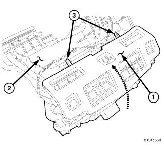
Courtesy of CHRYSLER GROUP, LLC
- Position the air distribution housing (1) into the vehicle.
- Install the air distribution housing onto the rear of the HVAC housing (2) by inserting the tabs on the bottom of the distribution housing into the slots located on the bottom of the HVAC housing and tipping the distribution housing forward until it is properly aligned with the HVAC housing.
- Connect the floor distribution ducts to the air distribution housing.
- Install the screws (3) that secure the air distribution housing to
the HVAC housing. Tighten the screws to 2.2 N.m (20 in. lbs.).
Fig. 82: Heater Core Removal & Installation
Courtesy of CHRYSLER GROUP, LLC - Install the heater core (4) into the driver side of the air distribution housing (2) and engage the heater core tubes (6) to the foam seal at the front of the HVAC housing (9).
- Install heater core retaining bracket (3) onto the air distribution housing and install the retaining screw (5). Tighten the screw to 2.2 N.m (20 in. lbs.).
- Install the flange (7) and two flange retaining screws (8). Tighten the screws to 2.2 N.m (20 in. lbs.).
- Install the blend door actuator (1) to the driver side of the air distribution housing. Refer to ACTUATOR, BLEND DOOR, INSTALLATION.
Fig. 83: Mode Door Actuator Removal/Installation
Courtesy of CHRYSLER GROUP, LLC - Connect the HVAC wire harness (1) to the mode door actuator (2) and
the blend door actuator (3) located on the driver side of the air
distribution housing (4).
NOTE: If the heater core is being replaced, flush the cooling system. Refer to STANDARD PROCEDURE .
- Install the HVAC housing assembly. Refer to HOUSING, HVAC, INSTALLATION.
HOUSING-AIR INLET
Courtesy of CHRYSLER GROUP, LLC
- Position the air inlet housing (3) onto the HVAC housing (6).
CAUTION: Make sure that the recirculation-air door pivot shaft is properly seated in the pivot seats located on the top of the HVAC housing.
- Install the five screws (5 and 7) that secure the air inlet housing to the HVAC housing. Tighten the screws to 2.2 N.m (20 in. lbs.).
- Inspect the foam seal (2), especially along the parting line (4). If the seal is deformed or damaged, it must be replaced.
- Connect the HVAC wire harness connector (8) to the recirculation door actuator (1).
- Install the HVAC housing assembly. Refer to HOUSING, HVAC, INSTALLATION.
HOUSING-FRESH AIR INLET
Courtesy of CHRYSLER GROUP, LLC
- Position the fresh air inlet housing (3), cabin air filter (1) and filter housing (4) as an assembly onto the engine compartment side of the dash panel (2).
- Install the two nuts (5) that secure the fresh air inlet housing and
filter housing to the dash panel. Tighten the nuts to 7 N.m (62 in.
lbs.).
Fig. 86: Push Pins-Fresh Air Inlet Housing
Courtesy of CHRYSLER GROUP, LLC - Position the insulator (4) into its installed location and install the push-pin retainer (5) that securesthe insulator to the front of the fresh air inlet housing (2).
- Install the push-pin retainer (1) that secures the fresh air inlet housing to the right inner fender (6).
- Reach under the fresh air inlet housing and install the wire harness
retainer (3) into the bottom of the air inlet housing, if equipped.
Fig. 87: Strut Support- Passenger Side
Courtesy of CHRYSLER GROUP, LLC - Position the powertrain control module (PCM) into its installed location.
- Position the strut support (3) into the engine compartment and loosely install the two bolts (1) that secure the strut support and the PCM to the passenger side strut tower (6).
- Install the purge solenoid (5) onto its mounting bracket located on the right strut tower.
- Engage the retainer that secures the wire harness (4) to the bottom of the strut support.
Fig. 88: Strut Support- Driver Side
Courtesy of CHRYSLER GROUP, LLC - Engage the wiper motor (5) to the bracket (4) located on the strut support (2).
- Position the strut support to the driver side strut tower and loosely install the two bolts (1) that secure the support to the tower.
- Tighten all four bolts that secure the strut support to 38 N.m (28 ft. lbs.).
- Install the cowl top panel onto the dash panel. Refer to COVER, COWL PANEL, INSTALLATION .
- Reconnect the negative battery cable.
HOUSING-HVAC ASSEMBLY
Courtesy of CHRYSLER GROUP, LLC
- Position the HVAC housing (2) into the passenger compartment with the mounting studs in their proper locations in the dash panel (5) and the condensate drain tube into the grommet (4) on the floor panel (3).
- Install the two nuts (1) that securethe HVAC housing to the passenger compartment side of the dash panel. Tighten the nuts to 3 N.m (26 in. lbs.).
- Install the defroster ducts. Refer to DUCT, DEFROSTER, INSTALLATION.
- Connect the rear floor distribution ducts. Refer to DUCT, FLOOR DISTRIBUTION, INSTALLATION.
- Connect the floor console duct. Refer to DUCT, FLOOR CONSOLE, INSTALLATION.
- Install the instrument panel. Refer to PANEL, INSTRUMENT, INSTALLATION
.
Fig. 90: Remove/Install HVAC Housing-Engine Compartment Side
Courtesy of CHRYSLER GROUP, LLC - Install the three nuts (1 and 3) that secure the HVAC housing to the engine compartment side of the dash panel (2). Tighten the nuts to 7 N.m (62 in. lbs.).
- Connect the heater hoses to the heater core tubes.
- Connect the A/C suction and liquid lines to the A/C evaporator. Refer to LINE, A/C LIQUID, INSTALLATION.
- Install the fresh air inlet housing to the engine compartment side of the dash panel. Refer to HOUSING, HVAC, INSTALLATION.
- Reconnect the negative battery cable.
- If the heater core was replaced, flush the cooling system. Refer to STANDARD PROCEDURE .
- Refill the engine cooling system. Refer to STANDARD PROCEDURE .
- Evacuate the refrigerant system. Refer to PLUMBING, STANDARD PROCEDURE.
- Charge the refrigerant system. Refer to PLUMBING, STANDARD PROCEDURE.
- Initiate the Actuator Calibration function using a scan tool. Refer to STANDARD PROCEDURE .
MOTOR, BLOWER
DESCRIPTION
DESCRIPTION
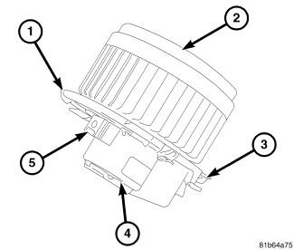
Courtesy of CHRYSLER GROUP, LLC
The blower motor is mounted to the bottom of the HVAC housing, on the passenger side of the vehicle. The blower motor assembly is a squirrel type blower cage (2) connected to a 12-volt, direct current (DC) motor located within a plastic housing (4). The blower motor has an integral wire harness bracket (1), three mounting provisions (3) and a wire connector receptacle (5).
The blower motor can be accessed for service from underneath the instrument panel.
OPERATION
OPERATION
The blower motor controls the velocity of air moving through the HVAC housing by spinning the blower wheel within the HVAC air inlet housing at the selected speed.
The Automatic Temperature Control (ATC) heating and A/C system has an electronic blower motor power module to control blower motor speed. The power module uses a Pulse Width Modulated (PWM) input from the A/C-heater control and a feedback signal from the blower motor to regulate the blower motor ground path. The blower motor receives battery current through the Totally Integrated Power Module (TIPM) whenever the ignition switch is in the Run position, and the blower motor control is in any position except Off.
The blower motor control system is diagnosed using a scan tool. Refer to STANDARD PROCEDURE .
The blower motor and blower motor wheel are factory balanced as an assembly and cannot be adjusted or repaired and must be replaced if inoperative or damaged.
DIAGNOSIS AND TESTING
DIAGNOSIS AND TESTING - BLOWER MOTOR
Disable the airbag system before attempting any steering wheel,
steering column or instrument panel component diagnosis or service.
Disconnect and isolate the negative battery (ground) cable and wait two
minutes for the airbag system capacitor to discharge before performing
further diagnosis or service. This is the only sure way to disable the
airbag system. Failure to follow these instructions may result in
accidental airbag deployment and possible serious or fatal injury.
WARNING:
See Wiring Information for circuit descriptions and diagrams.
NOTE:
NOISE
To determine if the blower motor is the source of the noise, simply switch the blower motor on and off. To verify that the blower motor is the source of the noise, unplug the blower motor wire harness connector and operate the heater and A/C system. If the noise goes away, possible causes include:
- Deformed or damaged blower wheel
- Foreign material in blower wheel
- Foreign material in HVAC housing
- Foreign material on fresh air inlet screen
- Improper blower motor mounting
- Worn blower motor bearings or brushes
VIBRATION
Possible causes of blower motor vibration include:
- Deformed or damaged blower wheel
- Improper blower motor mounting
- Foreign material in blower wheel
- Worn blower motor bearings
OPERATION
Possible causes of an inoperative blower motor include:
- Open fuse
- Inoperative blower motor
- Inoperative blower motor power module
- Inoperative blower motor switch
- Inoperative mode control switch
- Inoperative blower motor wiring or wire harness connectors
REMOVAL
REMOVAL
Disable the airbag system before attempting any steering wheel,
steering column, or instrument panel component diagnosis or service.
Disconnect and isolate the negative battery (ground) cable, then wait
two minutes for the airbag system capacitor to discharge before
performing further diagnosis or service. This is the only sure way to
disable the airbag system. Failure to take the proper precautions could
result in accidental airbag deployment and possible serious or fatal
injury.
WARNING:
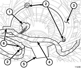
Courtesy of CHRYSLER GROUP, LLC
- Disconnect and isolate the negative battery cable.
- Remove the instrument panel silencer from the passenger side of the instrument panel. Refer to PANEL, SILENCER, REMOVAL .
- Disengage the wire harness connector locking tab and disconnect the wire harness connector (1) from the blower motor (5).
- Disengage the wire harness (4) from the two wire harness retainers (6).
- Remove the three screws (2) that secure the blower motor to the HVAC housing (3).
- Remove the blower motor from the HVAC housing.
INSTALLATION
INSTALLATION
Courtesy of CHRYSLER GROUP, LLC
- Position the blower motor (5) into the HVAC housing (3).
- Install the three screws (2) that secure the blower motor to the HVAC housing. Tighten the screws to 2.2 N.m (20 in. lbs.).
- Connect the wire harness connector (1) to the blower motor and engage the wire harness connector locking tab.
- Engage the HVAC wire harness onto the two wire harness retainers (6).
- Install the instrument panel silencer onto the passenger side of the instrument panel Refer to PANEL, SILENCER, INSTALLATION .
- Reconnect the negative battery cable.
OUTLET, AIR
REMOVAL
REMOVAL
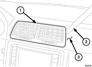
Courtesy of CHRYSLER GROUP, LLC
Center outlet shown in illustration. Other outlets similar.
NOTE:
- Gently pry on both sides of the instrument panel air outlet (1) being serviced using Trim Stick (special tool #C-4755, Trim Stick) (2) or equivalent until the air outlet snap clip retainers are released from the face of the instrument panel (3).
- Gently pull the air outlet from the instrument panel.
INSTALLATION
INSTALLATION
Courtesy of CHRYSLER GROUP, LLC
Center outlet shown in illustration. Other outlets similar.
NOTE:
- Position the air outlet (1) into its location on the instrument panel (3).
NOTE: Make sure that the foam seal on the outlet is properly installed and the air outlet is properly aligned to the duct within the instrument panel opening.
- Align the air outlet foam seal with the duct in the instrument panel and engage the outlet to the instrument panel. Gently push on the air outlet until the snap clip retainers on the outlet are fully engaged to the instrument panel.
PLUMBING
WARNING
WARNING
The A/C system contains refrigerant under high pressure. Repairs
should only be performed by qualified service personnel. Serious or
fatal injury may result from improper service procedures.
WARNING:
Avoid breathing the refrigerant and refrigerant oil vapor or mist.
Exposure may irritate the eyes, nose, and/or throat. Wear eye protection
when servicing the A/C refrigerant system. Serious eye injury can
result from direct contact with the refrigerant. If eye contact occurs,
seek medical attention immediately.
WARNING:
Do not expose the refrigerant to open flame. Poisonous gas is created
when refrigerant is burned. An electronic leak detector is recommended.
Serious or fatal injury may result from improper service procedures.
WARNING:
If accidental A/C system discharge occurs, ventilate the work area
before resuming service. Large amounts of refrigerant released in a
closed work area will displace the oxygen and cause suffocation and
serious or fatal injury.
WARNING:
The evaporation rate of R-134a refrigerant at average temperature and
altitude is extremely high. As a result, anything that comes in contact
with the refrigerant will freeze. Always protect the skin or delicate
objects from direct contact with the refrigerant.
WARNING:
The R-134a service equipment or the vehicle refrigerant system should
not be pressure tested or leak tested with compressed air. Some
mixtures of air and R-134a have been shown to be combustible at elevated
pressures. These mixtures are potentially dangerous, and may result in
fire or explosion causing property damage and serious or fatal injury.
WARNING:
The engine cooling system is designed to develop internal pressures
up to 145 kPa (21 psi). Do not remove or loosen the coolant pressure
cap, cylinder block drain plugs, radiator drain, radiator hoses, heater
hoses, or hose clamps while the engine cooling system is hot and under
pressure. Allow the vehicle to cool for a minimum of 15 minutes before
opening the cooling system for service. Failure to observe this warning
can result in serious burns from the heated engine coolant.
WARNING:
CAUTION
CAUTION
Never add R-12 to a refrigerant system designed to use R-134a. Do not
use R-12 equipment or parts on an R-134a A/C system. These refrigerants
are not compatible and damage to the A/C system will result.
CAUTION:
Never use R-12 refrigerant oil in an A/C system designed to use
R-134a refrigerant oil. These refrigerant oils are not compatible and
damage to the A/C system will result.
CAUTION:
The use of A/C system sealers may result in damage to A/C refrigerant
recovery/evacuation/recharging equipment and/or A/C system. Many
federal, state/provincial and local regulations prohibit the recharge of
A/C systems with known leaks. Chrysler LLC recommends the detection of
A/C system leaks through the use of approved leak detectors and
fluorescent leak detection dyes. Vehicles found with A/C system sealers
should be treated as contaminated and replacement of the entire A/C
refrigerant system is recommended. A/C systems found to be contaminated
with A/C system sealers, A/C stop-leak products or seal conditioners
voids the warranty for the A/C system.
CAUTION:
Recover the refrigerant before opening any fitting or connection.
Open the fittings with caution, even after the system has been
discharged. Never open or loosen a connection before recovering the
refrigerant.
CAUTION:
If equipped, do not remove the secondary retention clip from any
spring-lock coupler connection while the refrigerant system is under
pressure. Recover the refrigerant before removing the secondary
retention clip. Open the fittings with caution, even after the system
has been discharged. Never open or loosen a connection before recovering
the refrigerant.
CAUTION:
The internal parts of the A/C system will remain stable as long as
moisture-free refrigerant and refrigerant oil is used. Abnormal amounts
of dirt, moisture or air can upset the chemical stability. This may
cause operational troubles or even serious damage if present in more
than very small quantities. Before disconnecting a component, clean the
outside of the fittings thoroughly to prevent contamination from
entering the refrigerant system. Keep service tools and the work area
clean. Do not open the refrigerant system or uncap a replacement
component until you are ready to service the system. Immediately after
disconnecting a component from the refrigerant system, seal the open
fittings with a cap or plug. This will prevent contamination from
entering the A/C system.
CAUTION:
Refrigerant oil will absorb moisture from the atmosphere if left
uncapped. Do not open a container of refrigerant oil until you are ready
to use it. Replace the cap on the oil container immediately after
using. Store refrigerant oil only in a clean, airtight, and
moisture-free container.
CAUTION:
Do not overcharge the refrigerant system. Overcharging will cause
excessive compressor head pressure and can cause compressor noise and
A/C system failure.
CAUTION:
DIAGNOSIS AND TESTING
DIAGNOSIS AND TESTING - REFRIGERANT SYSTEM LEAKS
Review the safety precautions and warnings in this group before
performing this procedure. Failure to follow these instructions may
result in serious injury or death.
WARNING:
Do not expose the refrigerant to open flame. Poisonous gas is created
when refrigerant is burned. An electronic leak detector is recommended.
Serious or fatal injury may result from improper service procedures.
WARNING:
Use extreme care when working around a running engine. Keep hands and
fingers clear of the radiator fan, accessory drive belt and all other
moving components. Keep away when wearing loose clothing, jewelry or
long hair that is not properly secured. Underhood components may become
hot to the touch. Be careful not to come into contact with hot engine,
A/C and engine cooling system components. Failure to follow these
instructions may result in serious or fatal injury.
WARNING:
Always conduct the A/C Performance Test
prior to searching for an A/C refrigerant leak. Refer to DIAGNOSIS AND TESTING.
NOTE:
The A/C system in this vehicle comes
equipped from the factory with fluorescent refrigerant leak detection
dye installed in the refrigerant system.
NOTE:
When searching for a refrigerant leak in the A/C system, use an Ultra Violet (UV) light and an electronic leak detector that is designed for refrigerant used on this vehicle. It is important to use only high-quality refrigerant leak detection equipment to properly locate refrigerant system leaks, such as the equipment listed in the team PSE Service Equipment Catalog. When the use of additional leak detection dye is required, use only Chrysler LLC approved refrigerant leak detection dye, available through Mopar®.
LEAK TEST
- Begin searching for refrigerant leaks using a high quality UV light to detect the fluorescent refrigerant leak detection dye.
- Inspect all connections, plumbing fittings, brazed joints, hoses, hose crimps, service ports, compressor housing, pressure relief valve and A/C condenser for dye
- Inspect the evaporator drain tube and condensate for presence of dye, which indicates a leak from the A/C evaporator
- If equipped with rear A/C, inspect the underbody refrigerant lines, fittings, rear evaporator drain tube and condensate for presence of dye, which indicates a leak from the rear evaporator
- If no leaks are found using a UV light, proceed to step 2.
- If a leak is not found with the leak detection dye, operate the
heating and A/C system with the engine at idle under the following
conditions for at least 15 minutes, then proceed to step 3.
- Doors or windows open
- Transmission in Park or Neutral with the parking brake set (depending on transmission application)
- A/C and heater controls set to outside air, full cool, panel mode, high blower and A/C compressor engaged (If the A/C compressor does not engage, go to LOW OR EMPTY REFRIGERANT SYSTEM.
- If equipped with rear A/C, set rear controls to full cool and high blower
- Shut the vehicle off and wait at least 5 minutes.
- Insert the leak detector into the evaporator drain tube and the instrument panel air outlets, to check for evaporator leaks. Check the evaporator tubes at the A/C expansion valve, for leaks not visible behind the expansion valve. Check around the front of the A/C compressor, for compressor shaft seal leaks. Check between the A/C condenser and radiator for condenser leaks not previously visible.
- If equipped with rear A/C, insert the leak detector into the rear evaporator drain tube and rear air outlets. Check the underbody A/C lines and fittings, evaporator tubes and rear A/C expansion valve.
LOW OR EMPTY REFRIGERANT SYSTEM
This procedure should only be done after an
A/C Performance Test has been conducted and a refrigerant system leak
has NOT been found using the factory installed leak detection dye.
NOTE:
Do the following if the A/C compressor will not engage and a refrigerant leak in the A/C system is suspected. but cannot be found using the factory installed leak detection dye.
- Recover, evacuate and recharge the refrigerant system. Refer to PLUMBING, STANDARD PROCEDURE.
- Operate the heating and A/C system with the engine at idle under the following conditions for at least 15 minutes.
- Doors or windows open
- Transmission in Park or Neutral with the parking brake set (depending on transmission application)
- A/C and heater controls set to outside air, full cool, panel mode, high blower and A/C compressor engaged
- If equipped with rear A/C, set rear controls to full cool and high blower
- Shut the vehicle off and return to. Refer to LEAK TEST.
STANDARD PROCEDURE
R-134A REFRIGERANT SYSTEM RECOVERY

Courtesy of CHRYSLER GROUP, LLC
The R-134a refrigerant must be recovered from the A/C system prior to performing any repairs that require disconnection of an A/C refrigerant line.
When recovering the A/C refrigerant system, use an R-134a refrigerant recovery/recycling/charging station (1) that meets SAE standard J2788. Per SAE standard J2788, refrigerant recovery stations must recover 95% of the refrigerant system within 30 minutes at 21.1° C (70° F) and be able to measure the amount of refrigerant removed from the system to an accuracy of 28 grams (1 oz.). See the operating instructions supplied by the equipment manufacturer for proper care and use of this equipment.
A/C system should be tested prior to refrigerant recovery if the use
of A/C system sealants are suspected. These sealants have the potential
to clog refrigerant recovery equipment and cause vehicle A/C component
damage. Various tool manufacturers make tool kits that detect A/C system
sealants. See the operating instructions supplied by the equipment
manufacturer for proper care and use of this equipment.
NOTE:
If sealants are detected in an A/C system, the system should be treated as contaminated and replacement of the entire A/C refrigerant system is recommended. A/C systems found to be contaminated with A/C system sealers, A/C stop-leak products or seal conditioners void the warranty for the A/C system.
RECOVERY PROCEDURE
Review the safety precautions and warnings in this group before
performing this procedure. Failure to follow these instructions may
result in serious injury or death.
WARNING:
Various aftermarket manufacturers produce A/C system sealants that
are designed to stop A/C refrigerant system leaks. The use of A/C system
sealants may result in damage to A/C refrigerant
recovery/evacuation/recharging equipment and/or the vehicle A/C system
and are not recommended for use by Chrysler LLC.
CAUTION:
A small amount of refrigerant oil is removed from the A/C system each
time the refrigerant system is recovered and evacuated. Before charging
the A/C system, you MUST replenish any oil lost during the recovery
process. See the equipment manufacturer instructions for more
information.
CAUTION:
- If use of aftermarket A/C system sealant is suspected, the A/C system should be tested for sealant prior to refrigerant system recovery. See the operating instructions supplied by the equipment manufacturer for proper use and care of this equipment.
- Connect an R-134a refrigerant recovery/recycling/charging station that meets SAE standard J2788 to the refrigerant system.
- Recover the A/C refrigerant system following the operating instructions supplied by the recovery/recycling/charging station manufacturer.
- Disconnect the refrigerant recovery/recycling/charging station from the refrigerant system service ports.
- Reinstall the caps onto the refrigerant system service ports.
R-1234YF REFRIGERANT SYSTEM RECOVERY
Review the safety precautions and warnings in this group before
performing this procedure. Failure to follow these instructions may
result in serious injury or death.
WARNING:
Various aftermarket manufacturers produce A/C system sealants that
are designed to stop A/C refrigerant system leaks. The use of A/C system
sealants may result in damage to A/C refrigerant
recovery/evacuation/recharging equipment and/or the vehicle A/C system
and are not recommended for use by Chrysler LLC.
CAUTION:
Courtesy of CHRYSLER GROUP, LLC
When servicing the A/C system, an R-1234YF refrigerant recovery/recycling/charging station that meets SAE standard must be used. Per SAE standard, refrigerant recovery stations must recover 95% of the refrigerant system within 30 minutes at 21.1° C (70° F) and be able to measure the amount of refrigerant removed from the system to an accuracy of 28 grams (1 oz.). See the operating instructions supplied by the equipment manufacturer for proper care and use of this equipment.
A/C system should be tested prior to refrigerant recovery if the use
of A/C system sealants are suspected. These sealants have the potential
to clog refrigerant recovery equipment and cause vehicle A/C component
damage. Various tool manufacturers make tool kits that detect A/C system
sealants. See the operating instructions supplied by the equipment
manufacturer for proper care and use of this equipment.
NOTE:
If sealants are detected in an A/C system, the system should be treated as contaminated and replacement of the entire A/C refrigerant system is recommended. A/C systems found to be contaminated with A/C system sealers, A/C stop-leak products or seal conditioners void the warranty for the A/C system.
RECOVERY PROCEDURE
Review the safety precautions and warnings in this group before
performing this procedure. Failure to follow these instructions may
result in serious injury or death.
WARNING:
Various aftermarket manufacturers produce A/C system sealants that
are designed to stop A/C refrigerant system leaks. The use of A/C system
sealants may result in damage to A/C refrigerant
recovery/evacuation/recharging equipment and/or the vehicle A/C system
and are not recommended for use by Chrysler LLC.
CAUTION:
A small amount of refrigerant oil is removed from the A/C system each
time the refrigerant system is recovered and evacuated. Before charging
the A/C system, you MUST replenish any oil lost during the recovery
process. See the equipment manufacturer instructions for more
information.
CAUTION:
- If use of aftermarket A/C system sealant is suspected, the A/C system should be tested for sealant prior to refrigerant system recovery. See the operating instructions supplied by the equipment manufacturer for proper use and care of this equipment.
- Connect an R-1234YF refrigerant recovery/recycling/charging station that meets SAE standard to the refrigerant system.
- Recover the A/C refrigerant system following the operating instructions supplied by the recovery/recycling/charging station manufacturer.
- Disconnect the refrigerant recovery/recycling/charging station from the refrigerant system service ports.
- Reinstall the caps onto the refrigerant system service ports.
R-134A REFRIGERANT SYSTEM EVACUATE
Courtesy of CHRYSLER GROUP, LLC
If the A/C refrigerant system has been open to the atmosphere, it must be evacuated before the A/C system can be recharged with R-134a refrigerant.
Special effort must be used to prevent moisture from entering the A/C
system oil. Moisture in the oil is very difficult to remove and will
cause a reliability problem with the A/C compressor.
NOTE:
Moisture and air in the A/C refrigerant system will raise the compressor head pressure above acceptable operating levels. This will reduce the performance of the A/C system and damage the A/C compressor. Moisture will boil at near room temperature when exposed to vacuum. Always use an R-134a refrigerant recovery/recycling/charging station with a vacuum pump (1) that meets SAE standard J2788, or an R-134a compatible manifold gauge set and a stand-alone vacuum pump.
If an A/C compressor is left open to the atmosphere for an extended period of time, it is recommended that the refrigerant oil in the compressor be drained and replaced with new refrigerant oil to reduce the possibility of contaminating the refrigerant system. Refer to OIL, REFRIGERANT, STANDARD PROCEDURE.
R-134A EVACUATION PROCEDURE
Review the safety precautions and warnings in this group before
performing this procedure. Failure to follow these instructions may
result in serious injury or death.
WARNING:
A small amount of refrigerant oil is removed from the A/C system each
time the refrigerant system is recovered and evacuated. Before charging
the A/C system, you MUST replenish any oil lost during the recovery
process. See the equipment manufacturer instructions for more
information.
CAUTION:
- Recover the refrigerant system. Refer to PLUMBING, STANDARD PROCEDURE.
NOTE: When connecting service equipment couplers to refrigerant line service ports, verify that the valve of each coupler is fully closed prior to connecting. This will reduce the amount of effort required to make the connections.
- Connect an R-134a refrigerant recovery/recycling/charging station with a vacuum pump that meets SAE standard J2788 to the refrigerant system, or an R-134a compatible manifold gauge set and a stand-alone vacuum pump (depending on available equipment).
- Open the refrigerant recovery/recycling/charging station or manifold gauge set valves and start the vacuum pump. The vacuum pump should run a minimum of 45 minutes prior to recharge to eliminate all moisture in system. When the low-side gauge reads to the lowest degree of vacuum possible (approximately -88 kPa (-26 in. Hg) or greater) for 30 minutes, close all valves and turn off vacuum pump. If the refrigerant system fails to reach specified vacuum, the refrigerant system likely has a leak that must be corrected. If the refrigerant system maintains specified vacuum for at least 30 minutes, start the vacuum pump, open the valves and allow the refrigerant system to evacuate an additional 10 minutes.
- Close the refrigerant recovery/recycling/charging station or manifold gauge set valves. Turn off and disconnect the vacuum pump.
- Disconnect the refrigerant recovery/recycling/charging station or manifold gauge set from the refrigerant system service ports.
- Install the caps onto the refrigerant system service ports.
R-1234YF REFRIGERANT SYSTEM EVACUATE
Courtesy of CHRYSLER GROUP, LLC
If the A/C refrigerant system has been open to the atmosphere, it must be evacuated before the A/C system can be recharged with R-1234YF refrigerant.
Special effort must be used to prevent moisture from entering the A/C
system oil. Moisture in the oil is very difficult to remove and will
cause a reliability problem with the A/C compressor.
NOTE:
Moisture and air in the A/C refrigerant system will raise the compressor head pressure above acceptable operating levels. This will reduce the performance of the A/C system and damage the A/C compressor. Moisture will boil at near room temperature when exposed to vacuum. Always use an R-1234YF refrigerant recovery/recycling/charging station with a vacuum pump that meets SAE standard, or an R-1234YF compatible manifold gauge set and a stand-alone vacuum pump.
If an A/C compressor is left open to the atmosphere for an extended period of time, it is recommended that the refrigerant oil in the compressor be drained and replaced with new refrigerant oil to reduce the possibility of contaminating the refrigerant system. Refer to OIL, REFRIGERANT, STANDARD PROCEDURE.
EVACUATION PROCEDURE
Review the safety precautions and warnings in this group before
performing this procedure. Failure to follow these instructions may
result in serious injury or death.
WARNING:
A small amount of refrigerant oil is removed from the A/C system each
time the refrigerant system is recovered and evacuated. Before charging
the A/C system, you MUST replenish any oil lost during the recovery
process. See the equipment manufacturer instructions for more
information.
CAUTION:
- Recover the refrigerant system. Refer to PLUMBING, STANDARD PROCEDURE.
NOTE: When connecting service equipment couplers to refrigerant line service ports, verify that the valve of each coupler is fully closed prior to connecting. This will reduce the amount of effort required to make the connections.
- Connect an R-1234YF refrigerant recovery/recycling/charging station with a vacuum pump that meets SAE standard to the refrigerant system, or an R-1234YF compatible manifold gauge set and a stand-alone vacuum pump (depending on available equipment).
- Open the refrigerant recovery/recycling/charging station or manifold gauge set valves and start the vacuum pump. The vacuum pump should run a minimum of 45 minutes prior to recharge to eliminate all moisture in system. When the low-side gauge reads to the lowest degree of vacuum possible (approximately -88 kPa (-26 in. Hg) or greater) for 30 minutes, close all valves and turn off vacuum pump. If the refrigerant system fails to reach specified vacuum, the refrigerant system likely has a leak that must be corrected. If the refrigerant system maintains specified vacuum for at least 30 minutes, start the vacuum pump, open the valves and allow the refrigerant system to evacuate an additional 10 minutes.
- Close the refrigerant recovery/recycling/charging station or manifold gauge set valves. Turn off and disconnect the vacuum pump.
- Disconnect the refrigerant recovery/recycling/charging station or manifold gauge set from the refrigerant system service ports.
- Install the caps onto the refrigerant system service ports.
R-134A REFRIGERANT SYSTEM CHARGE
Courtesy of CHRYSLER GROUP, LLC
After all A/C refrigerant system repairs have been completed and the refrigerant system has been evacuated, the A/C system can be recharged with R-134a refrigerant.
When charging the A/C system, use an R-134a refrigerant recovery/recycling/charging station (1) that meets SAE standard J2788. Per SAE standard J2788, refrigerant recovery stations must charge the system to an accuracy of 14 grams (0.5 oz.). See the operating instructions supplied by the equipment manufacturer for proper care and use of this equipment.
R-134A CHARGING PROCEDURE
Review the safety precautions and warnings in this group before
performing this procedure. Failure to follow these instructions may
result in serious injury or death.
WARNING:
A small amount of refrigerant oil is removed from the A/C system each
time the refrigerant system is recovered and evacuated. Before charging
the A/C system, you MUST replenish any oil lost during the recovery
process. See the equipment manufacturer instructions for more
information.
CAUTION:
- Recover and evacuate the refrigerant system. Refer to PLUMBING, STANDARD PROCEDURE.
- Connect an R-134a refrigerant recovery/recycling/charging station that meets SAE standard J2788 to the refrigerant system.
- When required, adjust the refrigerant oil level. Refer to OIL, REFRIGERANT, STANDARD PROCEDURE.
NOTE: A/C system refrigerant capacity can be found on the HVAC Specification Label, located in the engine compartment.
- Measure the proper amount of refrigerant and heat it to 52° C (125° F) with the charging station. Refer to REFRIGERANT, SPECIFICATIONS. See the operating instructions supplied by the equipment manufacturer for proper use of this equipment.
- Open both the low and high side valves, then open the charge valve to allow the heated refrigerant to flow into the refrigerant system.
- When the transfer of refrigerant has stopped, close the valves.
WARNING: Take care not to open the high side (high pressure) valve while performing Step 7. Failure to follow these instructions may result in possible serious or fatal injury.
- Perform the following if all of the refrigerant charge did not transfer from the dispensing device.
- Open all of the windows in the vehicle.
- Set the heating and A/C system so that the A/C compressor is operating and the blower motor is operating at its lowest speed setting.
- Run the engine at a steady high idle (about 1400 RPM).
- If the A/C compressor does not operate, test the compressor control circuits and repair as required.
- Open the low side valve and the charge valve to allow the remaining refrigerant to flow into the refrigerant system.
- When the transfer of refrigerant has stopped, close the valves.
- Disconnect the refrigerant recovery/recycling/charging station from the refrigerant system service ports.
- Reinstall the caps onto the refrigerant system service ports.
R-1234YF REFRIGERANT SYSTEM CHARGE
Review the warnings and cautions for this system before performing
the procedure. Failure to follow these instructions may result in
serious injury or death.
WARNING:
The Underhood HVAC Specification Label contains the refrigerant fill specification of the vehicle being serviced.
NOTE:
Courtesy of CHRYSLER GROUP, LLC
After all refrigerant system leaks have been repaired and the refrigerant system has been evacuated, a refrigerant charge can be injected into the system. Refer to PLUMBING, STANDARD PROCEDURE.
When charging the A/C system, use an R-1234YF refrigerant recovery/recycling/charging station that meets SAE standard. Per SAE standard, refrigerant recovery stations must charge the system to an accuracy of 14 grams (0.5 oz.). See the operating instructions supplied by the equipment manufacturer for proper care and use of this equipment.
CHARGING PROCEDURE
Review the safety precautions and warnings in this group before
performing this procedure. Failure to follow these instructions may
result in serious injury or death.
WARNING:
A small amount of refrigerant oil is removed from the A/C system each
time the refrigerant system is recovered and evacuated. Before charging
the A/C system, you MUST replenish any oil lost during the recovery
process. See the equipment manufacturer instructions for more
information.
CAUTION:
- Recover and evacuate the refrigerant system. Refer to PLUMBING, STANDARD PROCEDURE.
- Connect an R-1234YF refrigerant recovery/recycling/charging station that meets SAE standard to the refrigerant system.
- When required, adjust the refrigerant oil level. Refer to OIL, REFRIGERANT, STANDARD PROCEDURE.
NOTE: A/C system refrigerant capacity can be found on the HVAC Specification Label, located in the engine compartment.
- Open both the low and high side valves, then open the charge valve to allow the refrigerant to flow into the refrigerant system.
- When the transfer of refrigerant has stopped, close the valves.
WARNING: Take care not to open the high side (high pressure) valve while performing Step 7. Failure to follow these instructions may result in possible serious or fatal injury.
- Perform the following if all of the refrigerant charge did not transfer from the dispensing device.
- Open all of the windows in the vehicle.
- Set the heating and A/C system so that the A/C compressor is operating and the blower motor is operating at its lowest speed setting.
- Run the engine at a steady high idle (about 1400 RPM).
- If the A/C compressor does not operate, test the compressor control circuits and repair as required.
- Open the low side valve and the charge valve to allow the remaining refrigerant to flow into the refrigerant system.
- When the transfer of refrigerant has stopped, close the valves.
- Disconnect the refrigerant recovery/recycling/charging station from the refrigerant system service ports.
- Install the caps onto the refrigerant system service ports.
COMPRESSOR, A/C
DESCRIPTION
A/C CLUTCH
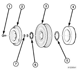
Courtesy of CHRYSLER GROUP, LLC
Typical A/C clutch assembly shown in illustration.
NOTE:
The A/C compressor clutch assembly consists of a stationary electromagnetic A/C clutch field coil (4), pulley bearing and pulley assembly (3), clutch plate (2) and shims (7). These components provide the means to engage and disengage the A/C compressor from the engine accessory drive belt.
The A/C clutch field coil and the pulley bearing and pulley assembly are both retained on the nose of the A/C compressor with snap rings (5 and 6). The clutch plate is splined to the compressor shaft and secured with a bolt (1).
A/C COMPRESSOR
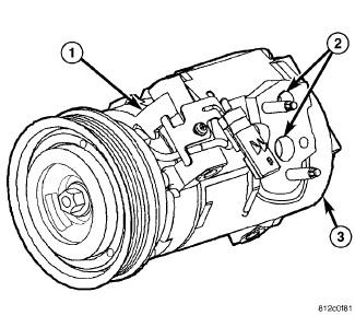
Courtesy of CHRYSLER GROUP, LLC
Typical Denso A/C compressor shown in illustration.
NOTE:
The A/C system on models equipped with the 3.6L engine use a Visteon RS-18 A/C Compressor (1). Models equipped with the 5.7L and 6.4L engine use a Denso 10SRE18 A/C Compressor. Both A/C compressors have the suction and discharge ports (2) located on the cylinder head (3).
A label identifying the use of R-134a refrigerant is located on each A/C compressor.
HIGH PRESSURE RELIEF VALVE
A high pressure relief valve is located on the compressor cylinder head at the rear of the A/C compressor. Refer to COMPRESSOR, A/C, DESCRIPTION. This mechanical valve is designed to vent refrigerant from the A/C system to protect against damage to the A/C compressor and other A/C system components caused by condenser air flow restriction or an overcharge of refrigerant.
OPERATION
A/C CLUTCH
The A/C clutch components provide the means to engage and disengage the A/C compressor from the moving engine accessory drive belt. A/C clutch engagement is controlled by the Powertrain Control Module (PCM). When the PCM energizes the electromagnetic A/C clutch coil, it magnetically draws the clutch plate into contact with the clutch pulley and drives the compressor shaft. When the coil is not energized, the pulley freewheels on the clutch hub bearing, which is part of the pulley assembly.
A/C clutch components cannot be repaired and must be replaced if inoperative or damaged.
A/C COMPRESSOR
The A/C compressor is driven by the engine through an electric clutch, drive pulley and belt arrangement. The A/C compressor is lubricated by refrigerant oil that is circulated throughout the refrigerant system with the refrigerant.
The A/C compressor draws in low-pressure refrigerant vapor from the A/C evaporator through its suction port. It then compresses the refrigerant into a high-pressure, high-temperature refrigerant vapor, which is then pumped to the A/C condenser through the compressor discharge port.
Be certain to adjust the refrigerant system oil level when replacing
an A/C compressor. Failure to properly adjust the refrigerant oil level
can prevent the A/C system from operating as designed and can cause
serious A/C compressor damage.
CAUTION:
The A/C compressor cannot be repaired and must be replaced if inoperative or damaged. The compressor clutch, pulley and bearing assembly, and clutch field coil are available for service. If an internal failure of the A/C compressor has occurred, the A/C receiver/drier must also be replaced. Refer to DRIER, A/C RECEIVER, REMOVAL.
HIGH PRESSURE RELIEF VALVE
The high pressure relief valve vents refrigerant from the A/C system when a discharge pressure of 3445 to 4135 kPa (500 to 600 psi) or above is reached. The high pressure relief valve closes with a minimum discharge pressure of 2756 kPa (400 psi) is reached.
The high pressure relief valve should not open when the A/C system is operating correctly. If the high pressure relief valve vents refrigerant, there is most likely a problem within the A/C refrigerant system. The high pressure relief valve vents only enough refrigerant to reduce the A/C system pressure, and then re-seats itself. If the high pressure relief valve vents refrigerant, see the A/C System Diagnosis chart. Refer to DIAGNOSIS AND TESTING.
The high pressure relief valve is factory-calibrated and cannot be adjusted or repaired, and must not be removed or otherwise disturbed. The valve is only serviced as a part of the A/C compressor.
DIAGNOSIS AND TESTING
A/C CLUTCH COIL
The A/C clutch coil electrical circuit is controlled by the Powertrain Control Module (PCM), through the Totally Integrated Power Module (TIPM). See Wiring Information for complete HVAC wiring diagrams. Begin testing of a suspected A/C clutch coil problem by performing the preliminary checks.
COIL RESISTANCE TEST
- Disconnect and isolate the negative battery cable.
- Disconnect the wire harness connector from the A/C clutch coil connector.
- Use an ohm meter and Back Probe Tool (special tool #6801, Terminal Probe) and measure the resistance of the A/C clutch coil at the coil connector terminals.
- See A/C Clutch Coil Specifications table for acceptable A/C clutch
coil resistance. Specifications apply for a work area temperature of
21° C (70° F).
- If the A/C clutch coil reading is below specifications, the coil is shorted and must be replaced.
- If the A/C clutch coil reading is above specifications, the coil is open and must be replaced.
COIL CURRENT DRAW TEST
- Verify the battery state of charge. Refer to BATTERY, DIAGNOSIS AND TESTING .
- Connect an ammeter (0 to 10 ampere scale selected) in series with the A/C clutch coil feed terminal using Back Probe Tool (special tool #6801, Terminal Probe). Connect a voltmeter (0 to 20 volt scale selected) to measure voltage across the battery and the A/C clutch coil.
- With the A/C heater control in the A/C mode and the blower motor at low speed, start the engine and allow it to run at a normal idle speed.
- The A/C clutch should engage immediately and the clutch coil supply voltage should be within two volts of the battery voltage. If the clutch coil supply voltage is OK, go to 5. If the coil supply voltage is not within two volts of battery voltage, test the clutch coil feed circuit for excessive voltage drop and repair as necessary.
- See A/C
Clutch Coil Specifications table for acceptable A/C clutch coil current
draw. Specifications apply for a work area temperature of 21° C (70°
F). If voltage is more than 12.5 volts, add electrical loads by turning
on electrical accessories until voltage reads below 12.5 volts.
- If the A/C clutch coil current reading is zero, the coil is open and must be replaced.
- If the A/C clutch coil current reading is above specifications, the coil is shorted and must be replaced.
A/C CLUTCH COIL SPECIFICATIONS
Application
Coil Resistance
Coil Current Draw
5.7L/6.4L Engines
3.3 - 3.5 ohms
3.2 amps Max @ 12V ± 0.5V @ 21° C (70° F)
3.6L Engine
3.0 - 4.0 ohms
3.1 - 4.0 amps @ 12V ± 0.5V @ 21° C (70° F)
PRELIMINARY CHECKS
- Using a scan tool, check for Diagnostic Trouble Codes (DTCs) in the A/C heater control, TIPM and PCM. If no DTCs are found, go to Step 2. If any DTCs are found, repair as required.
- If the A/C clutch still will not engage, verify the refrigerant charge level by conducting the A/C Performance test. Refer to DIAGNOSIS AND TESTING. If the refrigerant charge level is OK, go to COIL RESISTANCE TEST and COIL CURRENT DRAW TEST . If the refrigerant charge level is not OK, adjust the refrigerant charge as required.
A/C SYSTEM NOISE TESTING
When investigating an A/C system related noise, you must first know the conditions under which the noise occurs. These conditions include: weather, vehicle speed, transmission in gear or neutral, engine speed, engine temperature, and any other special conditions. Noises that develop during A/C operation can often be misleading. For example: What sounds like a failed front engine bearing or connecting rod, may be caused by loose bolts, nuts, mounting brackets or a loose compressor clutch assembly.
Drive belts are speed sensitive. At different engine speeds and depending upon drive belt tension, drive belts can develop noises that are mistaken for an A/C compressor noise. Improper drive belt tension can cause a misleading noise when the compressor clutch is engaged, which may not occur when the compressor clutch is disengaged. Check the accessory drive belt condition and tension as described in Cooling before beginning this procedure.
- Select a quiet area for testing. Duplicate the complaint conditions as much as possible. Turn the A/C compressor On and Off several times to clearly identify the compressor noise. Listen to the A/C compressor while the clutch is engaged and disengaged. Probe the A/C compressor with an engine stethoscope or a long screwdriver with the handle held to your ear to better localize the source of the noise.
- Loosen all of the compressor mounting hardware and retighten. Check the compressor clutch retainer. Be certain that the clutch field coil is mounted securely to the A/C compressor, and that the clutch plate and pulley are properly aligned and have the correct air gap. Refer to COMPRESSOR, A/C, INSTALLATION.
- To duplicate high-ambient temperature conditions (high head pressure), restrict the air flow through the A/C condenser. Install a manifold gauge set or a scan tool to be certain that the discharge pressure does not exceed 2760 kPa (400 psi).
- Check the refrigerant system plumbing for incorrect routing, rubbing or interference, which can cause unusual noises. Also check the refrigerant lines and hoses for kinks or sharp bends that will restrict refrigerant flow, which can cause noises.
- If the noise is from opening and closing of the high pressure relief valve, recover, evacuate and recharge the refrigerant system. Refer to PLUMBING, STANDARD PROCEDURE. and. Refer to PLUMBING, STANDARD PROCEDURE. Refer to PLUMBING, STANDARD PROCEDURE.
- If the high pressure relief valve still does not seat properly, replace the A/C compressor. Refer to COMPRESSOR, A/C, REMOVAL.
STANDARD PROCEDURE
STANDARD PROCEDURE - A/C CLUTCH PLATE INSPECTION
The A/C clutch can be serviced in the vehicle. The refrigerant system
can remain fully-charged during compressor clutch, pulley and bearing
assembly, or coil replacement.
NOTE:
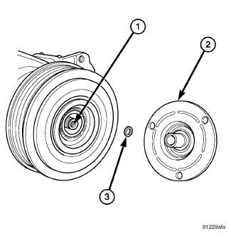
Courtesy of CHRYSLER GROUP, LLC
Examine the friction surfaces of the pulley and the clutch plate (2) for wear. The pulley and clutch plate should be replaced if excessive wear or scoring is found.
If the friction surfaces are oily, inspect the shaft and nose area of the A/C compressor (1) for refrigerant oil. If refrigerant oil is found, the compressor shaft seal is leaking and the A/C compressor must be replaced.
Check the pulley bearing for roughness or excessive leakage of grease. The pulley and clutch plate should be replaced if bearing roughness or excessive leakage is found.
REMOVAL
A/C CLUTCH
The compressor clutch assembly can be serviced with the refrigerant
system fully-charged and with the A/C compressor installed on the
engine.
NOTE:
Typical A/C compressor and clutch assembly shown in illustrations.
NOTE:
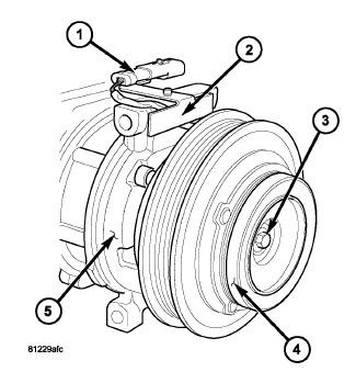
Courtesy of CHRYSLER GROUP, LLC
- Disconnect and isolate the negative battery cable.
- On 5.7L and 6.4L engine equipped models, remove the air intake hose and the air cleaner housing. Refer to BODY, AIR CLEANER, REMOVAL, 5.7L and BODY, AIR CLEANER, REMOVAL, 6.4L .
- Remove the radiator fan and shroud assembly. Refer to FAN, COOLING, REMOVAL .
- Remove the accessory drive belt. Refer to BELT, SERPENTINE, REMOVAL .
- Disconnect the engine wire harness from the compressor clutch field
coil connector (1) located on the top of the A/C compressor (5).
NOTE: Some models (depending on engine application) may require the A/C compressor to be removed from its installed location to gain access to the compressor shaft bolt and/or pulley and field coil snap rings. However, the refrigerant system can still remain fully charged.
- Carefully remove the A/C clutch coil connector and wire lead from the connector bracket (2).
- Remove the compressor shaft bolt (3). A band-type oil filter wrench
or a strap wrench may be used to hold the clutch plate (4) from rotating
during bolt removal.
Fig. 106: Identifying Compressor Shaft, Clutch Plate & Shim
Courtesy of CHRYSLER GROUP, LLCCAUTION: Do not pry between the clutch plate and the pulley and bearing assembly to remove the clutch plate from the compressor shaft as this may damage the clutch plate.
NOTE: Use care not to lose any clutch shim(s) during removal of the clutch plate, as they may be reused during the clutch plate installation process.
- Tap the clutch plate (2) lightly with a plastic mallet to release it
from the splines on the compressor shaft (1) and remove the clutch
plate and shim(s) (3).
Fig. 107: Clutch Pulley & Snap Ring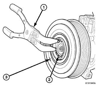
Courtesy of CHRYSLER GROUP, LLC - Using A/C Snap Ring Pliers (special tool #9764, Pliers, A/C Snap
Ring) (1) or equivalent, remove the snap ring (2) that secures the
pulley and bearing assembly (3) to the front of the A/C compressor and
remove the pulley and bearing assembly.
Fig. 108: Clutch Coil And Snap Ring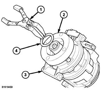
Courtesy of CHRYSLER GROUP, LLC - Using A/C Snap Ring Pliers (special tool #9764, Pliers, A/C Snap Ring) (1) or equivalent, remove the snap ring (4) that secures the A/C clutch coil (2) to the front of the A/C compressor (3) and remove the coil.
3.6L ENGINE
Review the warnings and cautions for this system before performing
the procedure. Failure to follow these instructions may result in
serious injury or death.
WARNING:
The A/C receiver/drier must be replaced if an internal failure of the
A/C compressor has occurred. Failure to replace the A/C receiver/drier
can cause serious damage to the replacement A/C compressor.
CAUTION:
The A/C compressor may be removed and repositioned without
disconnecting the refrigerant lines or discharging the refrigerant
system. Discharging is not necessary if servicing the A/C clutch, clutch
coil or engine.
NOTE:

Courtesy of CHRYSLER GROUP, LLC
Typical A/C compressor and refrigerant lines show.
NOTE:
- Disconnect and isolate the negative battery cable.
- Recover the refrigerant from the refrigerant system. Refer to PLUMBING, STANDARD PROCEDURE.
- Remove the air cleaner housing. Refer to BODY, AIR CLEANER, REMOVAL, 3.6L .
- Remove the accessory drive belt. Refer to BELT, SERPENTINE, REMOVAL .
- Disconnect the engine wire harness from the A/C clutch connector (1).
- Remove the nuts (2) that secure the A/C suction line (3) and A/C discharge line (4) to the A/C compressor (5).
- Disconnect the suction and discharge lines from the A/C compressor and remove and discard the dual plane seals.
- Install plugs in, or tape over all of the opened refrigerant line fittings and the compressor ports.
Fig. 110: Typical A/C compressor Mounting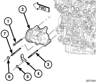
Courtesy of CHRYSLER GROUP, LLC - Remove the front belly pan. Refer to BELLY PAN, REMOVAL .
- Remove the two nuts (5 and 6) and two studs (3 and 7).
CAUTION: Use care not to deform or damage the heater tube and bracket when servicing the A/C compressor.
- Carefully position the heater tube and bracket (4) out of the way.
- Support the A/C compressor and remove the two bolts (1).
- Remove the A/C compressor from the engine compartment.
5.7L/6.4L ENGINES
Review the warnings and cautions for this system before performing
the procedure. Failure to follow these instructions may result in
serious injury or death.
WARNING:
The A/C receiver/drier must be replaced if an internal failure of the
A/C compressor has occurred. Failure to replace the A/C receiver/drier
can cause serious damage to the replacement A/C compressor.
CAUTION:
The A/C compressor may be removed and repositioned without
disconnecting the refrigerant lines or discharging the refrigerant
system. Discharging is not necessary if servicing the A/C clutch, clutch
coil or engine.
NOTE:
Courtesy of CHRYSLER GROUP, LLC
Typical A/C compressor and refrigerant lines shown in illustration.
NOTE:
- Disconnect and isolate the negative battery cable.
- Recover the refrigerant from the refrigerant system. Refer to PLUMBING, STANDARD PROCEDURE.
- Remove the air cleaner housing.
- Remove the accessory drive belt. Refer to BELT, SERPENTINE, REMOVAL .
- On SRT models, position the power steering pump and reservoir out of the way. Refer to RESERVOIR, POWER STEERING PUMP, REMOVAL .
- Remove the nuts (2) that secure the A/C suction line (3) and A/C discharge line (4) to the A/C compressor (5).
- Disconnect the suction and discharge lines from the A/C compressor and remove and discard the dual plane seals.
- Disconnect the engine wire harness from the A/C clutch connector (1).
- Install plugs in, or tape over all of the opened refrigerant line fittings and the compressor ports.
Fig. 112: Removing/Installing A/C Compressor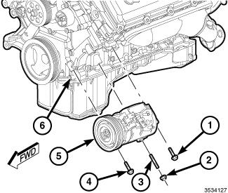
Courtesy of CHRYSLER GROUP, LLC - Remove the front belly pan.
- Remove the two bolts (1 and 4) that secure the A/C compressor (5) to the engine (6).
- Support the A/C compressor and remove the nut (2) and stud (3).
- Remove the A/C compressor from the engine compartment.
INSTALLATION
A/C CLUTCH
Typical A/C compressor and clutch assembly shown in illustrations.
NOTE:
Courtesy of CHRYSLER GROUP, LLC
- Align the dowel pin on the back of the A/C clutch coil (2) with the
hole in the front of the A/C compressor (3) and position the coil onto
the compressor. Be certain that the A/C clutch coil wire lead is
properly routed so that it is not pinched between the compressor housing
and the coil.
CAUTION: The snap ring must be fully and properly seated in the groove or it will vibrate out, resulting in a clutch failure and severe damage to the A/C compressor.
NOTE: A new snap ring must be used to secure the A/C clutch coil to the A/C compressor. The bevel side of the snap ring must face outward and both snap ring eyelets must be oriented to the right or to the left of the coil dowel pin location on the A/C compressor.
- Using A/C Snap Ring Pliers (special tool #9764, Pliers, A/C Snap
Ring) (1) or equivalent, install the snap ring (4) that secures the A/C
clutch coil to the front of the A/C compressor. Be certain that the snap
ring is fully and properly seated in the groove and oriented correctly.
Fig. 114: Identifying Pulley & Bearing Assembly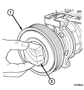
Courtesy of CHRYSLER GROUP, LLCCAUTION: Be certain to position the A/C clutch coil wire lead so that it is not damaged during A/C compressor pulley and bearing installation.
CAUTION: When installing the pulley and bearing assembly, DO NOT mar the friction surfaces of the pulley or premature failure of the clutch will result.
- Install the pulley and bearing assembly (1) onto the front of the
A/C compressor. If necessary, tap the pulley gently with a block of wood
(2) placed on the pulley friction surface.
Fig. 115: Clutch Pulley & Snap Ring
Courtesy of CHRYSLER GROUP, LLCCAUTION: The snap ring must be fully and properly seated in the groove or it will vibrate out, resulting in a clutch failure and severe damage to the A/C compressor.
NOTE: A new snap ring must be used to secure the pulley and bearing assembly to the A/C compressor. The bevel side of the snap ring must face outward.
- Using A/C Snap Ring Pliers (special tool #9764, Pliers, A/C Snap
Ring) (1) or equivalent, install the snap ring (2) that secures the
pulley and bearing assembly (3) to the front of the A/C compressor. Be
certain that the snap ring is fully and properly seated in the groove.
Fig. 116: Identifying Compressor Shaft, Clutch Plate & Shim
Courtesy of CHRYSLER GROUP, LLC - If the original clutch plate (2) and pulley and bearing assembly are
to be reused, reinstall the original shim(s) (3) onto the compressor
shaft (1). If a new clutch plate and pulley and bearing assembly are
being used, install a trial stack of shims 2.54 mm (0.010 in.) thick
onto the compressor shaft.
Fig. 117: Locating A/C Compressor Shaft Bolt
Courtesy of CHRYSLER GROUP, LLC - Install the clutch plate (4) onto the front of the A/C compressor (5).
- Install the compressor shaft bolt (3). Tighten the bolt to 19 N.m (168 in. lbs.).
NOTE: The shims may compress after tightening the shaft bolt. Check the air gap in four or more places to verify the air gap is correct. Spin the pulley before performing a final check of the air gap.
NOTE: On models with the clutch plate recessed into the pulley, use a 90° wire gap gauge to measure the clutch air gap. On other models, use a blade type feeler gauge to measure the air gap.
- With the clutch plate assembled tight against the shim(s), measure
the air gap between the clutch plate and the pulley and bearing
assembly. The air gap should be between 0.35 - 0.60 mm (0.014 - 0.024
in.). If the air gap is not between specifications, add or subtract
shims as needed until the correct air gap is obtained.
CAUTION: Be certain that the A/C clutch coil wire lead is routed so that it is not pinched between the compressor housing and the coil connector bracket.
- Carefully route the A/C clutch coil wire lead behind the connector bracket (2).
- Install the A/C clutch coil connector (1) onto the connector bracket.
- Connect the engine wire harness to the A/C clutch coil connector.
- Install the accessory drive belt. Refer to BELT, SERPENTINE, INSTALLATION .
- Install the radiator fan and shroud assembly. Refer to FAN, COOLING, INSTALLATION .
- On 5.7L and 6.4L engine equipped models, install the air cleaner housing and air intake hose. Refer to BODY, AIR CLEANER, INSTALLATION, 5.7L and BODY, AIR CLEANER, INSTALLATION, 6.4L .
- Reconnect the negative battery cable.
- Verify proper A/C clutch operation.
3.6L ENGINE
If the A/C compressor is being replaced, be certain to adjust the
refrigerant system oil level. Failure to properly adjust the refrigerant
oil level will prevent the A/C system from operating as designed and
can cause serious A/C compressor damage.
CAUTION:
The A/C receiver/drier must be replaced if an internal failure of the
A/C compressor has occurred. Failure to replace the A/C receiver/drier
can cause serious damage to the replacement A/C compressor.
CAUTION:
When replacing multiple A/C system components, see the Refrigerant
Oil Capacities chart to determine how much oil should be removed from
the new A/C compressor. Refer to OIL, REFRIGERANT, STANDARD PROCEDURE.
NOTE:
Replacement of the refrigerant line O-ring seals and gaskets is
required anytime a refrigerant line is disconnected. Failure to replace
the rubber O-ring seals and metal gaskets could result in a refrigerant
system leak.
NOTE:
Courtesy of CHRYSLER GROUP, LLC
- If the A/C compressor (2) is being replaced, the refrigerant oil in the old compressor must be first drained and measured. Then the oil in the new A/C compressor must be drained. Finally, the new compressor must be refilled with the same amount of new refrigerant oil that was drained out of the old compressor. When replacing multiple A/C system components, see the Refrigerant Oil Capacities chart to determine how much oil should be added to the refrigerant system. Refer to OIL, REFRIGERANT, STANDARD PROCEDURE. Use only refrigerant oil of the type recommended for the A/C compressor in the vehicle.
- Position the A/C compressor to the engine and install the two studs (3 and 7). Tighten the studs to 10 N.m (89 in. lbs.).
- Loosely install the two bolts (1)
- Reposition the heater tube and bracket (4) and loosely install the two nuts (5 and 6).
- Tighten the bolts and nuts to 28 N.m (21 ft. lbs.) using the following sequence:
- Bolt at front of compressor.
- Nut at front of compressor.
- Bolt at rear of compressor.
- Nut at rear of compressor.
- Install the front belly pan. Refer to BELLY PAN, INSTALLATION
.
Fig. 119: Remove/Install A/C Compressor Lines
Courtesy of CHRYSLER GROUP, LLCNOTE: Typical A/C compressor and refrigerant lines show.
- Remove the tape or plugs from the opened fittings on the A/C suction line (3) and the A/C discharge line (4) and the compressor ports.
- Lubricate new dual plane seals with clean refrigerant oil and install them onto the suction and the discharge line fittings. Use only the specified seals as they are made of a special material for the R-134a system. Use only refrigerant oil of the type recommended for the A/C compressor in the vehicle.
- Connect the suction and discharge lines onto the A/C compressor (5).
- Install the nuts (2) that secure the suction and discharge lines to the A/C compressor. Tighten the nuts to 23 N.m (17 ft. lbs.).
- Connect the engine wire harness to the A/C clutch connector (1).
- Install the accessory drive belt. Refer to BELT, SERPENTINE, INSTALLATION .
- Replace the A/C receiver/drier if the A/C compressor is being replaced due to an internal failure. Refer to DRIER, A/C RECEIVER, REMOVAL.
- Install the air cleaner housing. Refer to BODY, AIR CLEANER, INSTALLATION, 3.6L , .
- Reconnect the negative battery cable.
- Evacuate and charge the refrigerant system. Refer to PLUMBING, STANDARD PROCEDURE.
5.7L/6.4L ENGINES
If the A/C compressor is being replaced, be certain to adjust the
refrigerant system oil level. Failure to properly adjust the refrigerant
oil level will prevent the A/C system from operating as designed and
can cause serious A/C compressor damage.
CAUTION:
The A/C receiver/drier must be replaced if an internal failure of the
A/C compressor has occurred. Failure to replace the A/C receiver/drier
can cause serious damage to the replacement A/C compressor.
CAUTION:
When replacing multiple A/C system components, see the Refrigerant
Oil Capacities chart to determine how much oil should be removed from
the new A/C compressor. Refer to OIL, REFRIGERANT, STANDARD PROCEDURE.
NOTE:
Replacement of the refrigerant line O-ring seals and gaskets is
required anytime a refrigerant line is disconnected. Failure to replace
the rubber O-ring seals and metal gaskets could result in a refrigerant
system leak.
NOTE:
Courtesy of CHRYSLER GROUP, LLC
- If the A/C compressor (5) is being replaced, the refrigerant oil in the old compressor must be first drained and measured. Then the oil in the new A/C compressor must be drained. Finally, the new compressor must be refilled with the same amount of new refrigerant oil that was drained out of the old compressor. When replacing multiple A/C system components, see the Refrigerant Oil Capacities chart to determine how much oil should be added to the refrigerant system. Refer to OIL, REFRIGERANT, STANDARD PROCEDURE. Use only refrigerant oil of the type recommended for the A/C compressor in the vehicle.
- Position the A/C compressor to the engine (6) and install the stud (3). Tighten the stud to 10 N.m (89 in. lbs.).
- Loosely install the two bolts (1 and 4) and one nut (2) that secure the A/C compressor to the engine.
- Tighten the nut and bolts to 28 N.m (21 ft. lbs.) using the following sequence:
- Nut at front of compressor.
- Bolt at front of compressor.
- Bolt at rear of compressor.
- Install the front belly pan.
Fig. 121: Remove/Install A/C Compressor Lines
Courtesy of CHRYSLER GROUP, LLCNOTE: Typical A/C compressor and refrigerant lines shown in illustration.
- Connect the engine wire harness to the A/C clutch connector (1).
- Remove the tape or plugs from the opened fittings on the A/C suction line (3) and the A/C discharge line (4) and the compressor ports.
- Lubricate new dual plane seals with clean refrigerant oil and install them onto the suction and the discharge line fittings. Use only the specified seals as they are made of a special material for the R-134a system. Use only refrigerant oil of the type recommended for the A/C compressor in the vehicle.
- Connect the A/C suction and discharge lines onto the A/C compressor (5).
- Install the nuts (2) that secure the A/C suction and discharge lines
to the A/C compressor. Tighten the nuts to 23 N.m (17 ft. lbs.).
CAUTION: The A/C receiver/drier must be replaced if an internal failure of the A/C compressor has occurred. Failure to replace the A/C receiver/drier can cause serious damage to the replacement A/C compressor.
- On SRT models, reposition the power steering pump and reservoir. Refer to RESERVOIR, POWER STEERING PUMP, INSTALLATION .
- Install the accessory drive belt. Refer to BELT, SERPENTINE, INSTALLATION .
- Install the air cleaner housing.
- Reconnect the negative battery cable.
- Evacuate and charge the refrigerant system. Refer to PLUMBING, STANDARD PROCEDURE.
CONDENSER, A/C
DESCRIPTION
DESCRIPTION
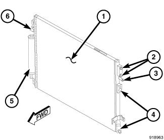
Courtesy of CHRYSLER GROUP, LLC
The A/C condenser (1) is located in the front of the engine compartment behind the front fascia. The A/C condenser is a heat exchanger that allows the high-pressure refrigerant gas being discharged by the A/C compressor to give up its heat to the air passing over the condenser fins, which causes the refrigerant to cool and change to a liquid state.
The A/C condenser is equipped with tapping blocks for the A/C refrigerant lines (4) and for the receiver/drier (5), integral mounting brackets (6), and fittings for an integral automatic transmission cooler (2) and power steering cooler (3), when equipped.
OPERATION
OPERATION
When air passes through the fins of the A/C condenser, the high-pressure refrigerant gas within the A/C condenser gives up its heat. The refrigerant then condenses as it leaves the A/C condenser and becomes a high-pressure liquid. The volume of air flowing over the condenser fins is critical to the proper cooling performance of the A/C system. Therefore, it is important that there are no objects placed in front of the radiator grille openings at the front of the vehicle or foreign material on the condenser fins that might obstruct proper air flow. Also, any factory-installed air seals or shrouds must be properly reinstalled following radiator or A/C condenser service.
Replacement of the refrigerant line O-ring seals and gaskets is
required anytime a refrigerant line is disconnected. Failure to replace
the rubber O-ring seals and metal gaskets could result in a refrigerant
system leak.
NOTE:
The A/C condenser has no serviceable parts. The O-ring seals used on the connections are made from a special type of rubber not affected by R-134a refrigerant. The O-ring seals and gaskets must be replaced whenever a refrigerant line is disconnected from the A/C condenser.
The A/C condenser cannot be repaired and must be replaced if leaking or damaged.
REMOVAL
REMOVAL
Review the warnings and cautions for this system before performing
the procedure. Failure to follow these instructions may result in
serious injury or death.
WARNING:
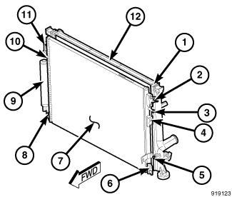
Courtesy of CHRYSLER GROUP, LLC
Illustration shown with A/C condenser and radiator removed from vehicle for clarity.
NOTE:
- Disconnect and isolate the negative battery cable.
- Recover the refrigerant from the refrigerant system. Refer to PLUMBING, STANDARD PROCEDURE.
- Remove the front fascia. Refer to FASCIA, FRONT, REMOVAL .
- When equipped, disconnect the automatic transmission cooler lines from the automatic transmission cooler ports (1) and install plugs in the cooler ports.
- When equipped, disconnect the power steering hoses from the power steering cooler fittings (3 and 10) and install plugs in the cooler ports.
- Disconnect the A/C discharge line and A/C liquid line from refrigerant line fittings (4 and 6) and. Refer to LINE, A/C LIQUID, REMOVAL. Refer to LINE, A/C DISCHARGE, REMOVAL.
- Install plugs in, or tape over, the opened refrigerant line fittings and condenser ports.
- Remove the four bolts (2, 5, 8 and 11) that secure A/C condenser (7) to the radiator (12).
- Carefully tilt the bottom of the A/C condenser forward and lower the condenser out of the vehicle.
- If required, place the A/C condenser onto a workbench and remove the A/C receiver/drier (9). Refer to DRIER, A/C RECEIVER, REMOVAL.
INSTALLATION
INSTALLATION
Be certain to adjust the refrigerant oil level when servicing the A/C
refrigerant system. Failure to properly adjust the refrigerant oil
level will prevent the A/C system from operating as designed and can
cause serious A/C compressor damage.
CAUTION:
When replacing multiple A/C system components, see the Refrigerant
Oil Capacities chart to determine how much oil should be added to the
refrigerant system. Refer to OIL, REFRIGERANT, STANDARD PROCEDURE.
NOTE:
If the A/C condenser is being replaced, add 30 milliliters (1 fluid
ounce) of refrigerant oil to the refrigerant system. Use only
refrigerant oil of the type recommended for the A/C compressor in the
vehicle.
NOTE:
Replacement of the refrigerant line O-ring seals and gaskets is
required anytime a refrigerant line is disconnected. Failure to replace
the rubber O-ring seals and metal gaskets may result in a refrigerant
system leak.
NOTE:
Be certain that each of the radiator and condenser air seals are
installed in their proper locations. These air seals are required for
the A/C and engine cooling systems to perform as designed.
NOTE:
Courtesy of CHRYSLER GROUP, LLC
Illustration shown with A/C condenser and radiator removed from vehicle for clarity.
NOTE:
- If required, install the A/C receiver/drier (9) onto the A/C condenser (7). Refer to DRIER, A/C RECEIVER, INSTALLATION.
- Carefully position the A/C condenser to the radiator (12).
- Install the four bolts (2, 5, 8 and 11) that secure the A/C condenser to the radiator. Tighten the bolts to 5 N.m (44 in. lbs.).
- Remove the tape or plugs from the opened refrigerant line fittings and condenser ports.
- Connect the A/C discharge line and the A/C liquid line to the refrigerant line tapping blocks (4 and 6) and. Refer to LINE, A/C DISCHARGE, INSTALLATION. Refer to LINE, A/C LIQUID, INSTALLATION.
- When equipped, remove the plugs and connect the power steering cooler lines to the power steering cooler fittings (3 and 10). Make sure the retaining clamps are fully engaged.
- When equipped, remove the plugs and connect the automatic transmission cooler lines to the cooler ports (1).
- Install the front fascia. Refer to FASCIA, FRONT, INSTALLATION .
- Reconnect the negative battery cable.
- Evacuate the refrigerant system. Refer to PLUMBING, STANDARD PROCEDURE.
- If the A/C condenser is being replaced, add 30 milliliters (1 fluid ounce) of refrigerant oil to the refrigerant system. When replacing multiple A/C system components, see the Refrigerant Oil Capacities chart to determine how much oil should be added to the refrigerant system. Refer to OIL, REFRIGERANT, STANDARD PROCEDURE. Use only refrigerant oil of the type recommended for the A/C compressor in the vehicle.
- Charge the refrigerant system. Refer to PLUMBING, STANDARD PROCEDURE.
- When equipped, check the automatic transmission and power steering fluid level and fill as required.
CORE, HEATER
DESCRIPTION
DESCRIPTION
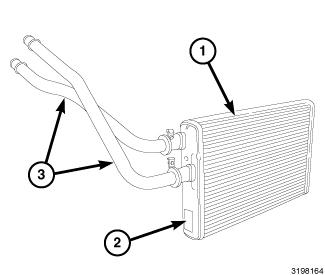
Courtesy of CHRYSLER GROUP, LLC
The heater core (1) is mounted into the left side of the air distribution housing, which is located behind the instrument panel. The heater core is a heat exchanger made of rows of tubes with fins. The heater core is positioned within the air distribution housing so that only the selected amount of air entering the housing passes through the heater core, before being distributed through the heating and A/C system ducts and outlets. One end of the heater core has a tank (2) that includes fittings for the heater core tubes (3).
The heater core tubes are not serviced separately from the heater core. The HVAC housing must be removed from the vehicle to service the heater core.
OPERATION
OPERATION
Engine coolant is circulated through the heater hoses to the heater core at all times. As the coolant flows through the heater core, heat is removed from the engine and is transferred to the heater core tubes and fins. Air directed through the heater core picks up the heat from the heater core fins. The blend-air door(s) allows control of the heater output air temperature by regulating the amount of air flowing through the heater core. The blower motor speed controls the volume of air flowing through the HVAC housing.
The heater core cannot be repaired and must be replaced if restricted, leaking or damaged.
REMOVAL
REMOVAL
Disable the airbag system before attempting any steering wheel,
steering column or instrument panel component diagnosis or service.
Disconnect and isolate the negative battery (ground) cable and wait two
minutes for the airbag system capacitor to discharge before performing
further diagnosis or service. This is the only sure way to disable the
airbag system. Failure to follow these instructions may result in
accidental airbag deployment and possible serious or fatal injury.
WARNING:
The heater core tubes are not serviced separately from the heater
core. The heater core tubes should not be repositioned, loosened or
removed from the heater core. Failure to follow this warning could
result in a coolant leak and possible serious or fatal injury.
WARNING:
Courtesy of CHRYSLER GROUP, LLC
- Remove the HVAC housing assembly and place it on a suitable workbench. Refer to HOUSING, HVAC, REMOVAL.
- On LHD models, remove the blend door actuator (1) from the driver side of the air distribution housing (2). Refer to ACTUATOR, BLEND DOOR, REMOVAL.
- Remove the two screws (8) that secure the flange (7) to the front of the HVAC housing (9) and remove the flange.
- Remove the screw (5) that secures the heater core retaining bracket (3) to the driver side of the air distribution housing and remove the bracket.
- Disengage the heater core tubes (6) from the foam seal at the front of the HVAC housing and carefully pull the heater core (4) straight out of the side of the air distribution housing.
INSTALLATION
INSTALLATION
The heater core tubes are not serviced separately from the heater
core. The heater core tubes should not be repositioned, loosened or
removed from the heater core. Failure to follow this warning could
result in a coolant leak and possible serious or fatal injury.
WARNING:
Courtesy of CHRYSLER GROUP, LLC
- Install the heater core (4) into the driver side of the air distribution housing (2) and engage the heater core tubes (6) to the foam seal at the front of the HVAC housing (9).
- Install heater core retaining bracket (3) onto the air distribution housing and install the retaining screw (5). Tighten the screw to 2.2 N.m (20 in. lbs.).
- Install the flange (7) and two flange retaining screws (8). Tighten the screws to 2.2 N.m (20 in. lbs.).
- On LHD models, install the blend door actuator (1) to the driver side of the air distribution housing. Refer to ACTUATOR, BLEND DOOR, INSTALLATION.
NOTE: If the heater core is being replaced, flush the cooling system. Refer to STANDARD PROCEDURE .
- Install the HVAC housing assembly. Refer to HOUSING, HVAC, INSTALLATION.
CORE, SERVICE PORT VALVE
DESCRIPTION
DESCRIPTION
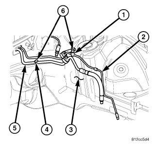
Courtesy of CHRYSLER GROUP, LLC
LHD model shown in illustration. RHD model similar.
NOTE:
Refrigerant system service ports are used to recover, recycle, evacuate, charge and test the A/C refrigerant system. Unique sizes are used on the two service ports for the R-134a refrigerant system to ensure the system is not accidentally contaminated with R-12 refrigerant or by service equipment used for R-12 refrigerant.
The high side service port (1) is located on the liquid line (2) near the left shock tower (3). The low side service port (4) is located on the suction line (5) near the left shock tower. Both the high side and low side A/C service port valve cores are serviceable.
The protective cap aids in service port sealing and helps protect the
refrigerant system from contamination. Remember to always reinstall the
protective cap onto the service port when refrigerant system service is
complete.
NOTE:
Each of the service ports has a threaded plastic protective cap (6) installed over it from the factory. The service port caps are serviceable items.
REMOVAL
REMOVAL
Review the warnings and cautions for this system before performing
the procedure. Failure to follow these instructions may result in
serious injury or death.
WARNING:
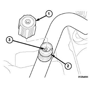
Courtesy of CHRYSLER GROUP, LLC
Typical A/C service port shown in illustration.
NOTE:
- Remove the protective cap (1) from the service port (2).
- Recover the refrigerant from the refrigerant system. Refer to PLUMBING, STANDARD PROCEDURE.
- Using a Schrader-type valve core tool, remove the valve core (3) from the service port.
- Install a plug in, or tape over the opened service port(s).
INSTALLATION
INSTALLATION
Courtesy of CHRYSLER GROUP, LLC
Typical A/C service port shown in illustration.
NOTE:
- Lubricate the valve core (3) with clean refrigerant oil prior to installation. Use only refrigerant oil of the type recommended for the A/C compressor in the vehicle.
- Remove the tape or plug from the service port (2).
CAUTION: Damage may result to a service port valve core if the valve core is not fully seated in the A/C service port. Such damage can result in a loss of refrigerant.
- Install and tighten the valve core into the service port(s) using a Schrader type valve core tool.
- Evacuate and charge the refrigerant system. Refer to PLUMBING, STANDARD PROCEDURE.
NOTE: The protective cap helps aid in service port sealing and helps protect the refrigerant system from contamination. Remember to always reinstall the protective cap onto the service port when refrigerant system service is complete.
- Install the protective cap (1) onto the service port.
DRIER, A/C RECEIVER
DESCRIPTION
DESCRIPTION
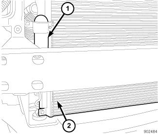
Courtesy of CHRYSLER GROUP, LLC
The receiver/drier (1) stores unnecessary refrigerant, filters the refrigerant, helps remove moisture from the refrigerant and retains any refrigerant vapor that may leave the A/C condenser (2) until it becomes a liquid. The receiver/drier is installed on the high-side of the A/C system and is connected directly to the right end of the A/C condenser. The receiver/drier can be easily serviced by removing the front fascia.
OPERATION
OPERATION
The A/C receiver/drier performs a filtering action to prevent foreign material in the refrigerant from contaminating the A/C expansion valve. Refrigerant enters the A/C receiver/drier as a high-pressure, low temperature liquid. Desiccant inside the A/C receiver/drier absorbs any moisture which may have entered and become trapped within the refrigerant system. In addition, during periods of high demand operation of the A/C system, the A/C receiver/drier acts as a reservoir to store surplus refrigerant.
Replacement of the refrigerant line O-ring seals and gaskets is
required anytime a refrigerant line is disconnected. Failure to replace
the rubber O-ring seals and metal gaskets could result in a refrigerant
system leak.
NOTE:
The A/C receiver/drier has no serviceable parts except for the O-ring seals, gaskets and the high side service port valve and cap. The O-ring seals used on the connections are made from a special type of rubber not affected by R-134a refrigerant. The O-ring seals and gaskets must be replaced whenever the A/C receiver/drier is removed.
The A/C receiver/drier cannot be repaired and must be replaced if leaking or damaged, or if an internal failure of the A/C compressor has occurred.
REMOVAL
REMOVAL
Review the warnings and cautions for this system before performing
the procedure. Failure to follow these instructions may result in
serious injury or death.
WARNING:
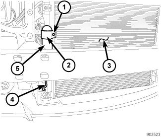
Courtesy of CHRYSLER GROUP, LLC
- Disconnect and isolate the negative battery cable.
- Recover the refrigerant from the refrigerant system. Refer to PLUMBING, STANDARD PROCEDURE.
- Remove the front fascia. Refer to FASCIA, FRONT, REMOVAL .
- Remove the screw (1) that secures the receiver/drier mounting bracket (2) to the right end of the A/C condenser (3).
- Remove the bolt (4) that secures the receiver/drier (5) to the A/C condenser.
- Disconnect the receiver/drier from the A/C condenser and remove and discard the dual-plane seal.
- Install plugs in, or tape over the opened receiver/drier fitting and the condenser ports.
INSTALLATION
INSTALLATION
Be certain to adjust the refrigerant oil level when servicing the A/C
refrigerant system. Failure to properly adjust the refrigerant oil
level prevents the A/C system from operating as designed and can cause
serious A/C compressor damage.
CAUTION:
The A/C receiver/drier must be replaced if an internal failure of the
A/C compressor has occurred. Failure to replace the A/C receiver/drier
can cause serious damage to the replacement A/C compressor.
CAUTION:
When replacing multiple A/C system components, refer to the
Refrigerant Oil Capacities chart to determine how much oil should be
added to the refrigerant system. Refer to OIL, REFRIGERANT, STANDARD PROCEDURE.
NOTE:
If only the A/C receiver/drier is being replaced, add 30 milliliters
(1 fluid ounce) of refrigerant oil to the refrigerant system. Use only
refrigerant oil of the type recommended for the A/C compressor in the
vehicle.
NOTE:
Replacement of the refrigerant line O-ring seals and gaskets is
required anytime a refrigerant line is disconnected. Failure to replace
the rubber O-ring seals and metal gaskets could result in a refrigerant
system leak.
NOTE:
Courtesy of CHRYSLER GROUP, LLC
- Position the receiver/drier (5) into the engine compartment.
- Remove the tape or plugs from the receiver/drier fitting and the ports of the A/C condenser (3).
- Lubricate a new dual-plane seal with clean refrigerant oil and install it onto the receiver/drier fitting. Use only the specified seal, as it is made of a special material for the system. Use only refrigerant oil of the type recommended for the A/C compressor in the vehicle.
- Connect the receiver/drier to the right end of the A/C condenser.
- Install the bolt (4) that secures the receiver/drier to the A/C condenser. Tighten the bolt to 22 N.m (16 ft. lbs.).
- Install the receiver/drier mounting bracket (2) onto the A/C condenser.
- Install the screw (1) securing the receiver/drier mounting bracket onto the A/C condenser. Tighten the screw to 5 N.m (44 in. lbs.).
- Install the front fascia. Refer to FASCIA, FRONT, INSTALLATION .
- Reconnect the negative battery cable.
- Evacuate the refrigerant system. Refer to PLUMBING, STANDARD PROCEDURE.
- If the A/C receiver/drier is being replaced, add 30 milliliters (1 fluid ounce) of refrigerant oil to the refrigerant system. When replacing multiple A/C system components, refer to the Refrigerant Oil Capacities chart to determine how much oil should be added to the refrigerant system. Refer to OIL, REFRIGERANT, STANDARD PROCEDURE. Use only refrigerant oil of the type recommended for the A/C compressor in the vehicle.
- Charge the refrigerant system. Refer to PLUMBING, STANDARD PROCEDURE.
EVAPORATOR, A/C
DESCRIPTION
DESCRIPTION
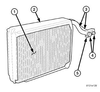
Courtesy of CHRYSLER GROUP, LLC
LHD model shown in illustration. RHD model similar.
NOTE:
The A/C evaporator (1) for the heating-A/C system is located within the HVAC housing, behind the instrument panel. The A/C evaporator and its insulator (2) are positioned in the HVAC housing so that all air entering the housing must pass over the evaporator fins before it is distributed through the heating-A/C system ducts and outlets. However, air passing over the evaporator fins will only be conditioned when the A/C compressor is engaged and circulating refrigerant through the A/C evaporator.
The A/C evaporator tubes (3) are connected and sealed to the A/C expansion valve by use of rubber O-rings (4) and a tapping block (5).
The A/C evaporator can only be serviced by removing and disassembling the HVAC housing assembly.
OPERATION
OPERATION
Refrigerant enters the A/C evaporator from the A/C expansion valve as a low-temperature, low-pressure mixture of liquid and gas. As air flows over the fins of the A/C evaporator, the humidity in the air condenses on the fins, and the heat from the air is absorbed by the refrigerant. Heat absorption causes the refrigerant to boil and vaporize. The refrigerant becomes a low-pressure gas when it leaves the A/C evaporator.
Replacement of the refrigerant line O-ring seals and gaskets is
required anytime a refrigerant line or expansion valve is disconnected.
Failure to replace the rubber O-ring seals and metal gaskets could
result in a refrigerant system leak.
NOTE:
The A/C evaporator has no serviceable parts except for the O-ring seals. The O-ring seals used on the connections are made from a special type of rubber not affected by refrigerant. The O-ring seals must be replaced whenever the A/C expansion valve is removed from the A/C evaporator.
The A/C evaporator cannot be repaired and must be replaced if leaking or damaged.
REMOVAL
REMOVAL
Courtesy of CHRYSLER GROUP, LLC
- Remove the HVAC housing assembly. Refer to HOUSING, HVAC, REMOVAL.
- Disassemble the HVAC housing as necessary to access the A/C evaporator (1). Refer to HOUSING, HVAC, DISASSEMBLY.
- Carefully lift the A/C evaporator and the foam seal (2) out of the lower half of the HVAC housing (3).
NOTE: If the foam seal at the front of the HVAC housing is deformed or damaged, the seal must be replaced.
- Remove the A/C expansion valve, tapping block and foam seal from the A/C evaporator. Refer to VALVE, A/C EXPANSION, REMOVAL.
INSTALLATION
INSTALLATION
Be certain to adjust the refrigerant oil level when servicing the A/C
refrigerant system. Failure to properly adjust the refrigerant oil
level will prevent the A/C system from operating as designed and can
cause serious A/C compressor damage.
CAUTION:
When replacing multiple A/C system components, see the Refrigerant
Oil Capacities chart to determine how much oil should be added to the
refrigerant system. Refer to OIL, REFRIGERANT, STANDARD PROCEDURE.
NOTE:
If the A/C evaporator is being replaced, add 60 milliliters (2 fluid
ounces) of refrigerant oil to the refrigerant system. Use only
refrigerant oil of the type recommended for the A/C compressor in the
vehicle.
NOTE:
Replacement of the refrigerant line O-ring seals and gaskets is
required anytime a refrigerant line is disconnected. Failure to replace
the rubber O-ring seals and metal gaskets could result in a refrigerant
system leak.
NOTE:
Courtesy of CHRYSLER GROUP, LLC
- Install the foam seal (2), tapping block and A/C expansion valve onto the A/C evaporator (1). Refer to VALVE, A/C EXPANSION, INSTALLATION.
- Install the A/C evaporator into the lower half of the HVAC housing (3). Make sure that the evaporator drain within the HVAC housing is clean and unrestricted and that the insulator around the A/C evaporator is properly installed.
- Assemble the HVAC housing. Refer to HOUSING, HVAC, ASSEMBLY.
NOTE: If the A/C evaporator is being replaced, add 60 milliliters (2 fluid ounces) of refrigerant oil to the refrigerant system. When replacing multiple A/C system components, see the Refrigerant Oil Capacities chart to determine how much oil should be added to the refrigerant system. Refer to OIL, REFRIGERANT, STANDARD PROCEDURE. Use only refrigerant oil of the type recommended for the A/C compressor in the vehicle.
- Install the HVAC housing assembly. Refer to HOUSING, HVAC, INSTALLATION.
LINE, A/C DISCHARGE
REMOVAL
REMOVAL
Review the warnings and cautions for this system before performing
the procedure. Failure to follow these instructions may result in
serious injury or death.
WARNING:
- Disconnect and isolate the negative battery cable.
- Recover the refrigerant from the refrigerant system. Refer to PLUMBING, STANDARD PROCEDURE.
- Remove the air cleaner housing. Refer to appropriate procedure, see BODY, AIR CLEANER, INSTALLATION, 3.6L
, BODY, AIR CLEANER, INSTALLATION, 5.7L
or BODY, AIR CLEANER, INSTALLATION, 6.4L
.
Fig. 137: A/C Discharge Line & Nut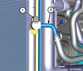
Courtesy of CHRYSLER GROUP, LLC - Reach through the headlamp opening in the upper radiator support and remove the nut (1) that secures the A/C discharge line (2) to the A/C condenser.
- Disconnect the A/C discharge line from the A/C condenser and remove and discard the dual plane seal.
- Install plugs in, or tape over the discharge line fitting and condenser inlet port.
Fig. 138: A/C Discharge Line & Nut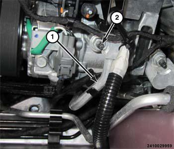
Courtesy of CHRYSLER GROUP, LLCNOTE: 3.6L A/C compressor and refrigerant lines shown in illustration.
- Remove the nut (2) that secures the A/C discharge line (1) to the A/C compressor.
- Disconnect the A/C discharge line from the A/C compressor and remove and discard the dual plane seal.
- Install plugs in, or tape over the opened refrigerant line fitting and the compressor port.
- Remove the A/C discharge line from the engine compartment.
INSTALLATION
INSTALLATION
Be certain to adjust the refrigerant oil level when servicing the A/C
refrigerant system. Failure to properly adjust the refrigerant oil
level will prevent the A/C system from operating as designed and can
cause serious A/C compressor damage.
CAUTION:
When replacing multiple A/C system components, refer to the
Refrigerant Oil Capacities chart to determine how much oil should be
added to the refrigerant system. Refer to OIL, REFRIGERANT, STANDARD PROCEDURE.
NOTE:
Replacement of the refrigerant line O-ring seals and gaskets is
required anytime a refrigerant line is disconnected. Failure to replace
the rubber O-ring seals and metal gaskets could result in a refrigerant
system leak.
NOTE:
Courtesy of CHRYSLER GROUP, LLC
- Position the A/C discharge line (1) into the engine compartment.
- Remove the tape or plugs from the opened fitting on the A/C discharge line and the outlet port on the A/C compressor.
- Lubricate a new dual plane seal with clean refrigerant oil and install it onto the discharge line fitting. Use only the specified seal as it is made of a special material for the system. Use only refrigerant oil of the type recommended for the A/C compressor in the vehicle.
- Install the A/C discharge line onto the A/C compressor.
- Install the nut (2) that secures the A/C discharge line to the A/C compressor. Tighten the nut to 23 N.m (17 ft. lbs.).
Fig. 140: A/C Discharge Line & Nut
Courtesy of CHRYSLER GROUP, LLC - Remove the tape or plugs from the opened discharge line fitting and the inlet port on the A/C condenser.
- Lubricate a new dual plane seal with clean refrigerant oil and install it onto the discharge line fitting. Use only the specified seal as it is made of a special material for the system. Use only refrigerant oil of the type recommended for the A/C compressor in the vehicle.
- Install the A/C discharge line (2) onto the A/C condenser.
- Reach through the headlamp opening in the upper radiator support and install the nut (1) that secures the A/C discharge line to the A/C condenser. Tighten the nut to 22 N.m (16 ft. lbs.).
- Install the air cleaner housing. Refer to appropriate procedure, see BODY, AIR CLEANER, INSTALLATION, 3.6L , BODY, AIR CLEANER, INSTALLATION, 5.7L or BODY, AIR CLEANER, INSTALLATION, 6.4L .
- Connect the negative battery cable.
- Evacuate the refrigerant system. Refer to PLUMBING, STANDARD PROCEDURE.
- Adjust the refrigerant oil level. Refer to OIL, REFRIGERANT, STANDARD PROCEDURE.
- Charge the refrigerant system. Refer to PLUMBING, STANDARD PROCEDURE.
LINE, A/C LIQUID
REMOVAL
LIQUID LINE
- Disconnect and isolate the negative battery cable.
- Recover the refrigerant from the refrigerant system. Refer to PLUMBING, STANDARD PROCEDURE.
- Remove the air cleaner housing. Refer to appropriate procedure, see BODY, AIR CLEANER, INSTALLATION, 3.6L , BODY, AIR CLEANER, INSTALLATION, 5.7L or BODY, AIR CLEANER, INSTALLATION, 6.4L .
- Raise and support the vehicle.
- Remove the front belly pan. Refer to BELLY PAN, REMOVAL
.
Fig. 141: A/C Liquid Line & Nut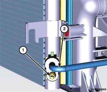
Courtesy of CHRYSLER GROUP, LLC - Remove the nut (1) that secures the A/C liquid line (2) to the A/C condenser.
- Disconnect the A/C liquid line from the A/C condenser and remove and discard the dual plane seal.
- Install plugs in, or tape over the opened liquid line fitting and condenser outlet port.
Fig. 142: A/C Suction Line & Nut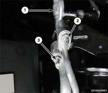
Courtesy of CHRYSLER GROUP, LLC - Lower the vehicle.
- Remove the nut (2) that secures the A/C liquid line to the Internal Heat Exchanger (1).
- Disconnect the A/C liquid line from the Internal Heat Exchanger and remove and discard the dual plane seal.
- Install plugs in, or tape over the opened liquid line fittings.
- Remove the A/C liquid line from the engine compartment.
INTERNAL HEAT EXCHANGER (IHX)
- Disconnect and isolate the negative battery cable.
- Recover the refrigerant from the refrigerant system. Refer to PLUMBING, STANDARD PROCEDURE.
- Remove the air cleaner housing. Refer to appropriate procedure, see BODY, AIR CLEANER, INSTALLATION, 3.6L
, BODY, AIR CLEANER, INSTALLATION, 5.7L
or BODY, AIR CLEANER, INSTALLATION, 6.4L
.
Fig. 143: A/C Suction Line & Nut
Courtesy of CHRYSLER GROUP, LLC - Remove the nuts (2 and 3) that secure the suction and liquid lines to the Internal Heat Exchanger (IHX) (1).
- Disconnect the suction and liquid lines from the IHX and remove and discard the dual plane seal.
- Install plugs in, or tape over the opened line fittings.
Fig. 144: Internal Heat Exchanger, Pressure Transducer & Harness Connector
Courtesy of CHRYSLER GROUP, LLC - Disconnect the wire harness (3) from the A/C pressure transducer (2).
Fig. 145: Refrigerant Line Mounting Bracket & Nut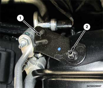
Courtesy of CHRYSLER GROUP, LLC - Remove the nut (2) that secures the refrigerant line mounting bracket (1) to the left front shock tower.
Fig. 146: IHX, A/C Expansion Valve & Nut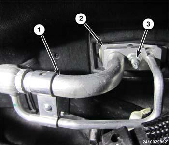
Courtesy of CHRYSLER GROUP, LLC - Remove the nut (3) that secures the IHX (1) to the A/C expansion valve (2).
- Disconnect the IHX from the A/C expansion valve.
- Remove the dual plane seal from the suction and liquid line fittings and discard.
- Install plugs in, or tape over the opened line fittings and the expansion valve ports.
- Remove the IHX from the engine compartment.
- If required, remove the A/C pressure transducer from the IHX. Refer to TRANSDUCER, A/C PRESSURE, REMOVAL.
INSTALLATION
LIQUID LINE
Courtesy of CHRYSLER GROUP, LLC
- Position the liquid line into the engine compartment.
- Remove the tape or plugs from the fittings that connect the liquid line to the Internal Heat Exchanger (1).
- Lubricate a new dual plane seal with clean refrigerant oil and install it onto the liquid line fitting. Use only the specified seal as it is made of a special material for the system. Use only refrigerant oil of the type recommended for the A/C compressor in the vehicle.
- Connect the A/C liquid line to the Internal Heat Exchanger.
- Install the nut (2) that secures the A/C liquid line to the Internal Heat Exchanger and tighten the nut to 22 N.m (16 ft. lbs.).
Fig. 148: A/C Liquid Line & Nut
Courtesy of CHRYSLER GROUP, LLC - Raise and support the vehicle.
- Remove the tape or plugs from the fitting on the liquid line (2) and the outlet port of the A/C condenser.
- Lubricate a new dual plane seal with clean refrigerant oil and install it onto the liquid line fitting. Use only the specified seal as it is made of a special material for the system. Use only refrigerant oil of the type recommended for the A/C compressor in the vehicle.
- Connect the A/C liquid line to the A/C condenser.
- Install the nut (1) that secures the front section of the A/C liquid line to the A/C condenser and tighten the nut to 22 N.m (16 ft. lbs.).
- Install the front belly pan. Refer to BELLY PAN, INSTALLATION .
- Lower the vehicle.
- Install the air cleaner housing. Refer to appropriate procedure, see BODY, AIR CLEANER, INSTALLATION, 3.6L , BODY, AIR CLEANER, INSTALLATION, 5.7L or BODY, AIR CLEANER, INSTALLATION, 6.4L .
- Connect the negative battery cable.
- Evacuate the refrigerant system. Refer to PLUMBING, STANDARD PROCEDURE.
- Adjust the refrigerant oil level. Refer to OIL, REFRIGERANT, STANDARD PROCEDURE.
- Charge the refrigerant system. Refer to PLUMBING, STANDARD PROCEDURE.
INTERNAL HEAT EXCHANGER (IHX)
- If removed, install the A/C pressure transducer onto the A/C liquid line. Refer to TRANSDUCER, A/C PRESSURE, INSTALLATION.
- Position the Internal Heat Exchanger (IHX) into the engine compartment.
- Remove the tape or plugs from the line fittings and the ports in the A/C expansion valve.
- Lubricate a new dual plane seal with clean refrigerant oil and
install it onto the suction and liquid line fittings. Use only the
specified seal as it is made of a special material for the system. Use
only refrigerant oil of the type recommended for the A/C compressor in
the vehicle.
Fig. 149: IHX, A/C Expansion Valve & Nut
Courtesy of CHRYSLER GROUP, LLC - Connect the IHX to the A/C expansion valve.
- Install the nut (3) that secures the IHX (1) to the A/C expansion valve (2) and tighten the nut to 23 N.m (17 ft. lbs.).
Fig. 150: Refrigerant Line Mounting Bracket & Nut
Courtesy of CHRYSLER GROUP, LLC - Install the nut (2) that secures the refrigerant line mounting
bracket (1) to the left front shock tower and tighten the nut to 11 N.m
(97 in. lbs.).
Fig. 151: Internal Heat Exchanger, Pressure Transducer & Harness Connector
Courtesy of CHRYSLER GROUP, LLC - Connect the wire harness (3) to the A/C pressure transducer (2).
- Remove the tape or plugs from the fittings that connect the suction and liquid lines to the IHX.
- Lubricate a new dual plane seal with clean refrigerant oil and
install it onto the liquid line fitting. Use only the specified seal as
it is made of a special material for the system. Use only refrigerant
oil of the type recommended for the A/C compressor in the vehicle.
Fig. 152: A/C Suction Line & Nut
Courtesy of CHRYSLER GROUP, LLC - Connect the suction and liquid lines to the IHX.
- Install the nuts (2 and 3) that secure the suction and liquid lines to the IHX and tighten the nut to 22 N.m (16 ft. lbs.).
- Install the air cleaner housing. Refer to appropriate procedure, see BODY, AIR CLEANER, INSTALLATION, 3.6L , BODY, AIR CLEANER, INSTALLATION, 5.7L or BODY, AIR CLEANER, INSTALLATION, 6.4L .
- Connect the negative battery cable.
- Evacuate the refrigerant system. Refer to PLUMBING, STANDARD PROCEDURE.
- Adjust the refrigerant oil level. Refer to OIL, REFRIGERANT, STANDARD PROCEDURE.
- Charge the refrigerant system. Refer to PLUMBING, STANDARD PROCEDURE.
LINE, A/C SUCTION
REMOVAL
SUCTION LINE
- Disconnect and isolate the negative battery cable.
- Recover the refrigerant from the refrigerant system. Refer to PLUMBING, STANDARD PROCEDURE.
- Remove the air cleaner housing. Refer to appropriate procedure, see BODY, AIR CLEANER, INSTALLATION, 3.6L
, BODY, AIR CLEANER, INSTALLATION, 5.7L
or BODY, AIR CLEANER, INSTALLATION, 6.4L
.
Fig. 153: Suction Line & Nut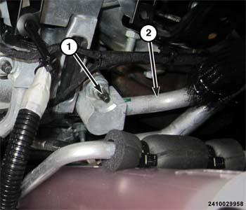
Courtesy of CHRYSLER GROUP, LLCNOTE: 3.6L compressor and refrigerant lines shown in illustration.
- Remove the nut (1) that secures the suction line (2) to the A/C compressor.
- Disconnect the A/C suction line from the A/C compressor and remove and discard the dual plane seal.
- Install plugs in, or tape over the opened suction line fitting and compressor inlet port.
Fig. 154: A/C Suction Line & Nut
Courtesy of CHRYSLER GROUP, LLC - Remove the nut (3) that secures the suction line to the Internal Heat Exchanger (IHX) (1).
- Disconnect the suction line from the IHX and remove and discard the dual plane seal.
- Install plugs in, or tape over the opened line fittings.
- Remove the suction line from the engine compartment.
INTERNAL HEAT EXCHANGER (IHX)
- Disconnect and isolate the negative battery cable.
- Recover the refrigerant from the refrigerant system. Refer to PLUMBING, STANDARD PROCEDURE.
- Remove the air cleaner housing. Refer to appropriate procedure, see BODY, AIR CLEANER, INSTALLATION, 3.6L
, BODY, AIR CLEANER, INSTALLATION, 5.7L
or BODY, AIR CLEANER, INSTALLATION, 6.4L
.
Fig. 155: A/C Suction Line & Nut
Courtesy of CHRYSLER GROUP, LLC - Remove the nuts (2 and 3) that secure the suction and liquid lines to the Internal Heat Exchanger (IHX) (1).
- Disconnect the suction and liquid lines from the IHX and remove and discard the dual plane seal.
- Install plugs in, or tape over the opened line fittings.
Fig. 156: Internal Heat Exchanger, Pressure Transducer & Harness Connector
Courtesy of CHRYSLER GROUP, LLC - Disconnect the wire harness (3) from the A/C pressure transducer (2).
Fig. 157: Refrigerant Line Mounting Bracket & Nut
Courtesy of CHRYSLER GROUP, LLC - Remove the nut (2) that secures the refrigerant line mounting bracket (1) to the left front shock tower.
Fig. 158: IHX, A/C Expansion Valve & Nut
Courtesy of CHRYSLER GROUP, LLC - Remove the nut (3) that secures the IHX (1) to the A/C expansion valve (2).
- Disconnect the IHX from the A/C expansion valve.
- Remove the dual plane seal from the suction and liquid line fittings and discard.
- Install plugs in, or tape over the opened line fittings and the expansion valve ports.
- Remove the IHX from the engine compartment.
- If required, remove the A/C pressure transducer from the IHX. Refer to TRANSDUCER, A/C PRESSURE, REMOVAL.
INSTALLATION
SUCTION LINE
- Position the front section of the suction line into the engine compartment.
- Remove the tape or plugs from the fittings that connect the suction line to the Internal Heat Exchanger (IHX).
- Lubricate a new dual plane seal with clean refrigerant oil and
install it onto the suction line fitting. Use only the specified seal as
it is made of a special material for the system. Use only refrigerant
oil of the type recommended for the A/C compressor in the vehicle.
Fig. 159: A/C Suction Line & Nut
Courtesy of CHRYSLER GROUP, LLC - Connect the suction line to the Internal IHX (1).
- Install the nut (3) that secures the suction line to the IHX and tighten the nut to 22 N.m (16 ft. lbs.).
- Remove the tape or plugs from the fitting on the suction line and the inlet port of the A/C compressor.
- Lubricate a new dual plane seal with clean refrigerant oil and
install it onto the suction line fitting. Use only the specified seal as
it is made of a special material for the system. Use only refrigerant
oil of the type recommended for the A/C compressor in the vehicle.
Fig. 160: Suction Line & Nut
Courtesy of CHRYSLER GROUP, LLCNOTE: 3.6L compressor and refrigerant lines shown in illustration.
- Connect the suction line (2) to the A/C compressor.
- Install the nut (1) that secures the suction line to the A/C compressor and tighten the nut to 23 N.m (17 ft. lbs.).
- Install the air cleaner housing. Refer to appropriate procedure, see BODY, AIR CLEANER, INSTALLATION, 3.6L , BODY, AIR CLEANER, INSTALLATION, 5.7L or BODY, AIR CLEANER, INSTALLATION, 6.4L .
- Connect the negative battery cable.
- Evacuate the refrigerant system. Refer to PLUMBING, STANDARD PROCEDURE.
- Adjust the refrigerant oil level. Refer to OIL, REFRIGERANT, STANDARD PROCEDURE.
- Charge the refrigerant system. Refer to PLUMBING, STANDARD PROCEDURE.
INTERNAL HEAT EXCHANGER (IHX)
- If removed, install the A/C pressure transducer onto the A/C liquid line. Refer to TRANSDUCER, A/C PRESSURE, INSTALLATION.
- Position the Internal Heat Exchanger (IHX) into the engine compartment.
- Remove the tape or plugs from the line fittings and the ports in the A/C expansion valve.
- Lubricate a new dual plane seal with clean refrigerant oil and
install it onto the suction and liquid line fittings. Use only the
specified seal as it is made of a special material for the system. Use
only refrigerant oil of the type recommended for the A/C compressor in
the vehicle.
Fig. 161: IHX, A/C Expansion Valve & Nut
Courtesy of CHRYSLER GROUP, LLC - Connect the IHX to the A/C expansion valve.
- Install the nut (3) that secures the IHX (1) to the A/C expansion valve (2) and tighten the nut to 23 N.m (17 ft. lbs.).
Fig. 162: Refrigerant Line Mounting Bracket & Nut
Courtesy of CHRYSLER GROUP, LLC - Install the nut (2) that secures the refrigerant line mounting
bracket (1) to the left front shock tower and tighten the nut to 11 N.m
(97 in. lbs.).
Fig. 163: Internal Heat Exchanger, Pressure Transducer & Harness Connector
Courtesy of CHRYSLER GROUP, LLC - Connect the wire harness (3) to the A/C pressure transducer (2).
- Remove the tape or plugs from the fittings that connect the suction and liquid lines to the IHX.
- Lubricate a new dual plane seal with clean refrigerant oil and
install it onto the liquid line fitting. Use only the specified seal as
it is made of a special material for the system. Use only refrigerant
oil of the type recommended for the A/C compressor in the vehicle.
Fig. 164: A/C Suction Line & Nut
Courtesy of CHRYSLER GROUP, LLC - Connect the suction and liquid lines to the IHX.
- Install the nuts (2 and 3) that secure the suction and liquid lines to the IHX and tighten the nut to 22 N.m (16 ft. lbs.).
- Install the air cleaner housing. Refer to appropriate procedure, see BODY, AIR CLEANER, INSTALLATION, 3.6L , BODY, AIR CLEANER, INSTALLATION, 5.7L or BODY, AIR CLEANER, INSTALLATION, 6.4L .
- Connect the negative battery cable.
- Evacuate the refrigerant system. Refer to PLUMBING, STANDARD PROCEDURE.
- Adjust the refrigerant oil level. Refer to OIL, REFRIGERANT, STANDARD PROCEDURE.
- Charge the refrigerant system. Refer to PLUMBING, STANDARD PROCEDURE.
OIL, REFRIGERANT
STANDARD PROCEDURE
STANDARD PROCEDURE - REFRIGERANT OIL LEVEL
When an A/C system is assembled at the factory, all components except the A/C compressor are refrigerant oil free. After the refrigerant system has been charged and operated, the refrigerant oil in the A/C compressor is dispersed throughout the refrigerant system. The receiver/drier, A/C evaporator, A/C condenser and the A/C compressor will each retain a significant amount of the needed refrigerant oil.
It is important to have the correct amount of refrigerant oil in the A/C system. This ensures proper lubrication of the A/C compressor. Too little oil will result in damage to the A/C compressor, while too much oil will reduce the cooling capacity of the A/C system and consequently result in higher discharge air temperatures.
The refrigerant oil in the A/C system is
unique depending on the A/C compressor used. Use only PAG oils that are
designed to work with the refrigerant type and A/C compressor in the
vehicle. Always refer to the A/C Underhood Specification Label for the
correct oil designation. The refrigerant oil container should be kept
tightly capped until it is ready for use, and then tightly recapped
after use to prevent contamination from dirt and moisture. Refrigerant
oil will quickly absorb any moisture it comes in contact with,
therefore, special effort must be used to keep all system components
moisture-free. Moisture in the refrigerant oil is very difficult to
remove and will cause a reliability problem with the A/C compressor.
NOTE:
Most reclaim/recycling equipment will measure the lubricant being
removed during recovery. This amount of lubricant should be added back
into the system. Refer to the reclaim/recycling equipment manufacturers
instructions.
NOTE:
It will not be necessary to check the oil level in the A/C compressor or to add oil, unless there has been an oil loss. An oil loss may occur due to a rupture or leak from a refrigerant line, a connector fitting, a component, or a component seal. If a leak occurs, add 30 milliliters (1 fluid ounce) of refrigerant oil to the refrigerant system after the repair has been made. Refrigerant oil loss will be evident at the leak point by the presence of a wet, shiny surface around the leak.
Refrigerant oil must be added when an A/C condenser, A/C evaporator or A/C receiver/drier is replaced. See the Refrigerant Oil Capacities chart.
The refrigerant oil level in a new A/C compressor must first be adjusted prior to compressor installation.
REFRIGERANT OIL TYPE
A/C Compressor
Oil Type
Denso 10SRE18 - 5.7L/6.4L Engines
ND-12 PAG oil*
Visteon RS-18 - 3.6L Engine
VC-46 PAG oil*
*Always use the type of PAG oil listed for the model being serviced. See A/C Underhood Specification Label located in the engine compartment. Do not mix different types of PAG oils.
REFRIGERANT OIL CAPACITIES
COMPONENT
ml.
oz.
Total System Fill
120
4.1
A/C Condenser
30
1.0
A/C Evaporator
60
2.0
A/C Receiver/drier
30
1.0
A/C Compressor
Drain and measure the oil from the old compressor (See Compressor Oil Drain Procedure)
COMPRESSOR OIL DRAIN PROCEDURE
Be certain to adjust the refrigerant system oil level when replacing
an A/C compressor. Failure to properly drain and measure the refrigerant
oil from the A/C compressor can prevent the A/C system from operating
as designed and cause serious compressor damage.
CAUTION:
The A/C compressor is filled with refrigerant oil from the factory. Use the following procedure to drain and measure refrigerant oil from the A/C compressor.
- Drain all of the refrigerant oil from the old A/C compressor into a clean measured container.
- Drain all of the refrigerant oil from the new A/C compressor into a clean measured container.
- Refill the new A/C compressor with the same amount of refrigerant oil that was drained out of the old compressor. Use only clean refrigerant oil of the type specified for the A/C compressor in the vehicle.
- Install the new A/C compressor onto the engine. Refer to COMPRESSOR, A/C, INSTALLATION.
REFRIGERANT
SPECIFICATIONS
SPECIFICATIONS
REFRIGERANT CHARGE CAPACITY
Application
Capacity
R-134a
681 g (1.50 lbs.)
R-1234yf
709 g (1.56 lbs.)
VALVE, A/C EXPANSION
DESCRIPTION
DESCRIPTION
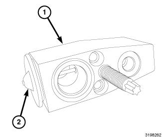
Courtesy of CHRYSLER GROUP, LLC
The A/C expansion valve controls the amount of refrigerant entering the A/C evaporator. The A/C expansion valve is of a thermostatic expansion valve (TXV) design and consists of an aluminum H-valve type body (1), with an integral thermal sensor (2). The A/C expansion valve is located at the dash panel between the A/C refrigerant lines and the A/C evaporator.
OPERATION
OPERATION
The A/C expansion valve controls the high-pressure, low temperature liquid refrigerant from the A/C liquid line and converts it into a low-pressure, low-temperature mixture of liquid and gas before it enters the A/C evaporator. A mechanical sensor in the A/C expansion valve monitors the temperature and pressure of the refrigerant leaving the A/C evaporator through the A/C suction line, and adjusts the orifice size at the liquid line port to let the proper amount of refrigerant into the evaporator to meet the vehicle A/C cooling requirements. Controlling the refrigerant flow through the A/C evaporator ensures that none of the refrigerant leaving the A/C evaporator is still in a liquid state, which could damage the A/C compressor.
Replacement of the refrigerant line O-ring seals is required anytime a
refrigerant line is disconnected from the expansion valve. Failure to
replace the rubber O-ring seals could result in a refrigerant system
leak.
NOTE:
The A/C expansion valve is factory calibrated and cannot be adjusted or repaired and must be replaced if inoperative or damaged.
DIAGNOSIS AND TESTING
DIAGNOSIS AND TESTING - A/C EXPANSION VALVE
Review the warnings and cautions for this system before performing
the procedure. Failure to follow these instructions may result in
serious injury or death.
WARNING:
The A/C expansion valve should only be tested following testing of the A/C compressor.
NOTE:
Liquid CO2
is required to test the A/C expansion valve. This material is available from most welding supply facilities. Liquid CO2
is also available from companies which service and sell fire extinguishers.
NOTE:
When testing the A/C expansion valve, the work area and the vehicle temperature must be 21° to 27°C (70° to 85°F). To test the expansion valve:
- Connect a charging station or manifold gauge set to the refrigerant system service ports. Refer to PLUMBING, STANDARD PROCEDURE.
- Verify the refrigerant system charge level by conducting the A/C Performance Test. Refer to DIAGNOSIS AND TESTING.
- Close all doors, windows and vents to the passenger compartment.
- Set the A/C-heater controls so that the A/C compressor is operating, the temperature control is in the highest temperature position, the mode-air doors is directing air output to the floor and the blower motor operating is operating at the highest speed.
- Start the engine and allow it to idle. After the engine has reached normal operating temperature, allow the passenger compartment to heat up. This will create the need for maximum refrigerant flow into the A/C evaporator.
- If the refrigerant charge is sufficient, the discharge (high
pressure) gauge should read 827 kPa to 1655 kPa (120 psi to 240 psi).
The suction (low pressure) gauge should read 207 kPa to 345 kPa (30 psi
to 50 psi). If OK, go to 7. If not OK, replace the inoperative A/C expansion valve.
WARNING: Protect the skin and eyes from exposure to liquid CO2 or personal injury can result.
- If the suction (low pressure) gauge reads within the specified range, freeze the A/C expansion valve for 30 seconds using liquid CO2 or another suitable super-cold material. Do not spray R-134a or R-12 refrigerant on the A/C expansion valve for this test. The suction (low pressure) gauge reading should drop by 69 kPa (10 psi). If OK, go to 8. If not OK, replace the inoperative A/C expansion valve. Refer to VALVE, A/C EXPANSION, REMOVAL.
- Allow the A/C expansion valve to thaw. The suction (low pressure) gauge reading should stabilize at 207 kPa to 345 kPa (30 psi to 50 psi). If not OK, replace the inoperative A/C expansion valve. Refer to VALVE, A/C EXPANSION, REMOVAL.
REMOVAL
REMOVAL
Review the warnings and cautions for this system before performing
the procedure. Failure to follow these instructions may result in
serious injury or death.
WARNING:
LHD model shown in illustration. RHD model similar.
NOTE:
- Disconnect and isolate the negative battery cable.
- Recover the refrigerant from the refrigerant system. Refer to PLUMBING, STANDARD PROCEDURE.
- Remove the Internal Heat Exchanger (IHX). Refer to LINE, A/C LIQUID, REMOVAL.
- Install plugs in, or tape over the opened suction and liquid line fittings.
Fig. 166: A/C Expansion Valve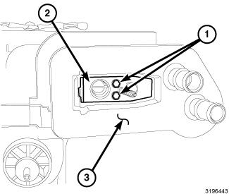
Courtesy of CHRYSLER GROUP, LLC - Remove the two bolts (1) that secure the A/C expansion valve (2) to the evaporator tube tapping block located within the seal (3).
- Remove the A/C expansion valve from the evaporator tube tapping block.
- Remove the O-ring seals from the evaporator tube fittings and discard.
- Install plugs in, or tape over the opened evaporator tube fittings.
INSTALLATION
INSTALLATION
Be certain to adjust the refrigerant oil level when servicing the A/C
refrigerant system. Failure to properly adjust the refrigerant oil
level will prevent the A/C system from operating as designed and can
cause serious A/C compressor damage.
CAUTION:
When replacing multiple A/C system components, see the Refrigerant
Oil Capacities chart to determine how much oil should be added to the
refrigerant system. Refer to OIL, REFRIGERANT, STANDARD PROCEDURE.
NOTE:
Replacement of the refrigerant line O-ring seals and gaskets is
required anytime a refrigerant line is disconnected. Failure to replace
the rubber O-ring seals and metal gaskets could result in a refrigerant
system leak.
NOTE:
LHD model shown in illustration. RHD model similar.
NOTE:
Courtesy of CHRYSLER GROUP, LLC
- Remove the tape or plugs from the evaporator tube fittings and all of the expansion valve ports.
- Lubricate new O-ring seals with clean refrigerant oil and install them onto the evaporator tube fittings. Use only the specified O-ring seals as they are made of a special material for the R-134a system. Use only refrigerant oil of the type recommended for the A/C compressor in the vehicle.
- Install the A/C expansion valve (2) onto the evaporator tube tapping block.
- Install the two bolts (1) that secure the A/C expansion valve to the evaporator tube tapping block. Tighten the bolts to 11 N.m (97 in. lbs.).
- Remove the tape or plugs from the suction and liquid line fittings.
- Lubricate a new seal with clean refrigerant oil and install onto the suction and liquid line fittings. Use only the specified seal as it is made of a special material for the system. Use only refrigerant oil of the type recommended for the A/C compressor in the vehicle.
- Install the Internal Heat Exchanger (IHX). Refer to LINE, A/C LIQUID, INSTALLATION.
- Connect the negative battery cable.
- Evacuate the refrigerant system. Refer to PLUMBING, STANDARD PROCEDURE.
- Adjust the refrigerant oil level. Refer to OIL, REFRIGERANT, STANDARD PROCEDURE.
- Charge the refrigerant system. Refer to PLUMBING, STANDARD PROCEDURE.